
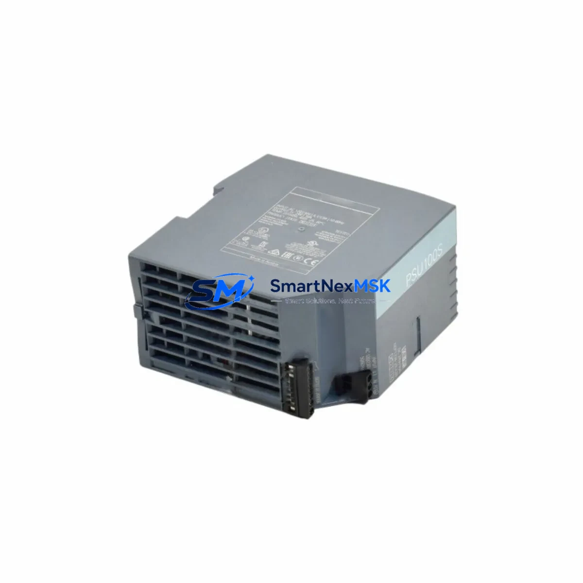
Siemens 6EP1334-2BA20 Retrofit-Ready PSU for SITOP Control Systems: Compatible Modernization & Smooth Legacy Upgrade
The Siemens 6EP1334-2BA20 is a SITOP PSU100S series 24 VDC / 10 A stabilized power supply unit engineered for demanding industrial environments. As aging control cabinets face end-of-life challenges, this module has become a cornerstone retrofit component for engineers replacing discontinued or degraded power supplies in SIMATIC S7-300 and S7-400 automation platforms. Whether you are modernizing a legacy production line, recovering from an unplanned power module failure, or executing a planned control cabinet upgrade, the 6EP1334-2BA20 delivers the electrical performance and form factor compatibility required for a low-risk, minimal-downtime transition.
Rated for 85–264 VAC wide-range input, the unit outputs a regulated 24 VDC at up to 10 A continuous load, making it directly interchangeable with earlier SITOP generations such as the 6EP1334-1SL11 and 6EP1334-2BA10 in most panel configurations. Its compact DIN-rail mounting profile fits standard 35 mm rails without mechanical modification, and the screw-terminal block layout is compatible with existing field wiring in the majority of retrofit scenarios encountered in automotive, chemical, water treatment, and discrete manufacturing facilities.
Upgrade Compatibility Table
| Parameter | 6EP1334-2BA20 (This Unit) | Retrofit Notes |
|---|---|---|
| Output Voltage | 24 VDC regulated | Direct replacement for 24 V SITOP predecessors |
| Output Current | 10 A continuous | Verify total load of connected S7-300 CPU, SM modules, and field devices |
| Input Voltage Range | 85–264 VAC / 110–300 VDC | Wide-range; no tap switching required |
| Mounting | 35 mm DIN rail | Compatible with standard S7-300 mounting rails and third-party DIN enclosures |
| Terminal Wiring | Screw terminals, 2.5 mm² | Matches legacy SITOP terminal pitch; re-use existing ferrule-terminated cables |
| Communication Interface | None (standalone PSU) | No protocol migration required; pairs with CP 343-1, CP 443-1 communication processors |
| Common Replacements | 6EP1334-2BA10, 6EP1334-1SL11 | Verify output connector polarity and load capacity before swap |
| Commissioning Requirement | No firmware configuration | Power-on verification via SIMATIC Manager or TIA Portal diagnostics sufficient |
| Warranty | 12 Months | Covered from date of shipment; includes functional test certificate |
Retrofit Planning for Existing Automation Systems
A successful retrofit begins well before the 6EP1334-2BA20 arrives on site. Engineers should audit the existing control cabinet to confirm total power consumption across all installed modules. In a typical S7-300 rack, this includes the CPU 314C-2 DP or CPU 315-2 PN/DP, digital input/output modules such as the SM 321 and SM 322, analog modules like the SM 331 and SM 332, and any installed function modules or communication processors. The aggregate 24 VDC load — including field sensor loops, solenoid valves, and indicator lamps fed from the same bus — must remain within the 10 A rated output of the replacement unit.
Terminal block mapping is the next critical step. Document the existing wiring layout using the original panel drawings before disconnecting any conductors. The 6EP1334-2BA20 uses the same L+/M/PE terminal arrangement as its predecessors, so in most cases the existing cable harness can be transferred directly. Where ferrule crimping standards differ between the old and new unit, re-terminate conductors to the 2.5 mm² screw terminal specification to ensure reliable contact resistance.
For systems that include a SIMATIC ET 200S or ET 200M distributed I/O island connected via PROFIBUS DP, confirm that the IM 151-1 or IM 153-2 interface module receives stable 24 VDC from the local panel supply rather than from the central rack PSU. This isolation prevents a single PSU failure from cascading across the distributed network. Similarly, if the control system uses a CP 343-1 Lean or CP 343-1 Advanced for Industrial Ethernet connectivity, verify that the communication processor’s 24 VDC supply rail is correctly fused and separated from high-inrush actuator loads.
Backplane and rack integrity should be inspected during the retrofit window. The S7-300 mounting rail and bus connector system — including the U-connector links between CPU, power supply, and signal modules — should be checked for oxidation or mechanical stress. Replacing a degraded PSU is an ideal opportunity to reseat all bus connectors and verify that the rack ground bonding meets IEC 60204-1 requirements.
Where the legacy system includes an OP 7, OP 17, or TP 177B HMI panel communicating via MPI or PROFIBUS, confirm that the HMI’s 24 VDC supply is independently sourced or adequately budgeted within the new PSU’s load calculation. HMI screen loss during a PSU swap is a common oversight that extends commissioning time unnecessarily.
All units supplied by SMARTNEXMSK are functionally tested prior to shipment. Each 6EP1334-2BA20 is verified for output voltage regulation, overcurrent protection response, and inrush current behavior. A test certificate accompanies every shipment, and the 12-month warranty covers both component failure and workmanship defects from the date of delivery.
Downtime Control During System Migration
Minimizing production downtime during a PSU replacement requires a structured changeover plan. The recommended approach is to pre-stage the 6EP1334-2BA20 alongside the existing panel, perform a complete backup of the S7-300 or S7-400 program using SIMATIC Manager or TIA Portal before any power interruption, and confirm that the backup includes all data blocks, organization blocks, and hardware configuration files. This ensures that if the CPU loses its retentive memory during the power transition, the program can be reloaded within minutes rather than hours.
Where process continuity is critical — for example, in continuous chemical dosing or conveyor sequencing applications — coordinate the PSU swap with a planned maintenance window and notify downstream systems. If the control system architecture includes a redundant CPU pair such as the S7-400H with a UR2-H rack, the PSU replacement can often be performed on one redundancy path while the other maintains control, effectively achieving a hot-swap without process interruption.
After installing the 6EP1334-2BA20, restore power incrementally: energize the PSU first with no load connected, verify 24 VDC output at the terminals, then reconnect the CPU and signal modules in sequence. Monitor the SIMATIC diagnostic buffer for any startup faults related to module addressing or configuration mismatches. If the system uses a CP 343-1 for SCADA connectivity, confirm that the Ethernet link re-establishes and that the SCADA historian resumes data collection before releasing the system to production.
Field calibration of analog I/O channels connected through SM 331 or SM 332 modules should be verified after the PSU swap, as supply voltage transients during changeover can occasionally shift analog reference baselines. A brief loop check against known process values confirms signal integrity before full production restart.
Retrofit Support FAQ
Q1: Is the 6EP1334-2BA20 a direct drop-in replacement for the 6EP1334-2BA10?
In the majority of installations, yes. Both units share the same 24 VDC / 10 A output rating, DIN-rail mounting footprint, and terminal block layout. The 2BA20 revision incorporates updated internal components for improved efficiency and EMC compliance, but the electrical interface is backward compatible. Verify your existing load budget and terminal wiring before swapping.
Q2: Does this unit require any firmware configuration or address assignment?
No. The 6EP1334-2BA20 is a standalone power supply with no configurable firmware, PROFIBUS address, or network parameters. Installation is purely mechanical and electrical. After wiring, power-on verification through the SIMATIC diagnostic buffer or a handheld multimeter is sufficient to confirm correct operation.
Q3: What pre-shipment testing is performed, and what does the 12-month warranty cover?
Every unit undergoes functional testing including output voltage regulation under load, overcurrent protection trip verification, and inrush current measurement. A test certificate is included with each shipment. The 12-month warranty covers manufacturing defects and functional failures under normal operating conditions from the date of delivery. It does not cover damage resulting from incorrect installation, overvoltage events, or environmental exposure beyond the rated IP20 enclosure protection.
Q4: Can this PSU support a mixed rack with both digital and analog signal modules?
Yes. The 6EP1334-2BA20 is suitable for powering mixed S7-300 racks containing SM 321 digital input, SM 322 digital output, SM 331 analog input, and SM 332 analog output modules simultaneously, provided the total 24 VDC load remains within the 10 A rated output. For racks with high analog module counts or additional field device loads, calculate the worst-case current draw and consider supplementing with a SITOP PSU8200 or a secondary 6EP1333-2BA20 (5 A) unit for isolated analog supply rails.
© 2026 SMARTNEXMSK. All rights reserved.
Original Source: https://smartnexmsk.com
Contact: [email protected] | +86 18259474341



