
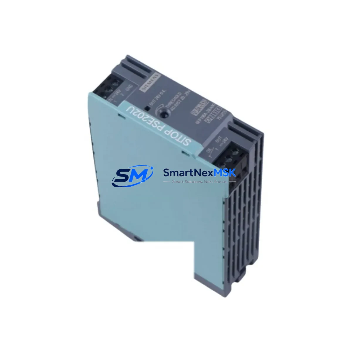
Siemens 6EP1964-2BA00 Retrofit-Ready Redundancy for SITOP Control Systems
The Siemens 6EP1964-2BA00 is a SITOP redundancy module engineered for mission-critical industrial power distribution systems where uninterrupted operation is non-negotiable. Designed to work in parallel with SITOP PSU300S and SITOP PSU8600 series power supply units, this module enables seamless load sharing and automatic failover — ensuring that a single power supply failure does not interrupt your production line, control cabinet, or field device network.
For facilities running legacy Siemens S7-300 or S7-400 PLC platforms, the 6EP1964-2BA00 is a proven retrofit component that integrates directly into existing 24 VDC distribution architectures without requiring panel redesign. Engineers replacing aging SITOP SMART or SITOP modular units will find this module fully compatible with standard DIN rail mounting and existing terminal wiring layouts, significantly reducing retrofit labor time and minimizing the risk of wiring errors during changeover.
When planning a retrofit around the 6EP1964-2BA00, engineers should verify the total connected load across both upstream power supply units — typically a pair of SITOP PSU300S 20A or 40A modules — to confirm that the redundancy module’s current balancing capacity is not exceeded. Terminal block compatibility with existing field wiring (typically 2.5 mm² to 6 mm² conductors) should be confirmed before installation. The module’s output terminals are designed for direct connection to the downstream 24 VDC bus, and no additional fusing is required at the redundancy stage if upstream SITOP units are already protected.
In S7-300 and S7-400 control cabinet upgrades, the 6EP1964-2BA00 is commonly installed alongside a SITOP UPS1600 uninterruptible power supply module to provide both redundancy and buffer capacity. This combination protects CPU modules such as the CPU 315-2 PN/DP or CPU 416-3 PN/DP from voltage dips during load transients or upstream supply switching. For newer TIA Portal-based systems migrating from STEP 7 Classic, the power architecture remains compatible, and no program logic changes are required solely due to the addition of this redundancy module.
Communication-intensive panels that include CP 343-1 or CP 443-1 PROFINET communication processors, or IM 153-2 PROFIBUS remote I/O interface modules, benefit particularly from redundant power architectures. A single power supply failure in these configurations can cause network segment dropouts that trigger cascading faults across distributed I/O racks. The 6EP1964-2BA00 eliminates this failure mode by maintaining continuous 24 VDC output even when one supply unit is removed for maintenance or replacement.
For systems incorporating ET 200M or ET 200S distributed I/O stations connected via PROFIBUS DP or PROFINET IO, the redundancy module ensures that remote rack power remains stable during local cabinet maintenance windows. This is especially valuable in process industries where field instruments, valve positioners, and transmitters must remain energized even when control cabinet work is in progress.
Retrofit planners should also account for the SITOP SEL1400 selective current limiting module if the downstream 24 VDC distribution feeds multiple branch circuits. The SEL1400 works in conjunction with the 6EP1964-2BA00 to provide per-branch fault isolation, preventing a short circuit on one output branch from collapsing the entire 24 VDC bus. This combination is strongly recommended for control cabinets powering more than four independent field device circuits.
Upgrade Compatibility Table
| Parameter | Details |
|---|---|
| SKU / Part Number | 6EP1964-2BA00 |
| Brand / Manufacturer | Siemens |
| Product Series | SITOP Redundancy |
| Compatible Power Supplies | SITOP PSU300S, SITOP PSU8600, SITOP modular 20A/40A |
| Output Voltage | 24 VDC |
| Mounting | DIN Rail (35 mm), standard panel mounting |
| Communication Compatibility | PROFIBUS DP, PROFINET IO (passive power layer — no protocol dependency) |
| PLC Platform Compatibility | Siemens S7-300, S7-400, S7-1500 (24 VDC supply architectures) |
| Replacement / Retrofit Path | Direct drop-in for legacy SITOP SMART redundancy units |
| Installation Requirement | Verify upstream PSU current rating; no additional fusing required at redundancy stage |
| Commissioning Note | Balance load across both PSU units before energizing; confirm LED status indicators post-installation |
| Warranty | 12 Months — covers manufacturing defects and functional failure under normal operating conditions |
Retrofit Planning for Existing Automation Systems
A successful retrofit centered on the 6EP1964-2BA00 begins with a thorough audit of the existing power distribution architecture. Engineers should document the current draw of all connected loads — including CPU racks, I/O modules, HMI panels such as the Siemens TP700 Comfort or KTP900 Basic, and any third-party field devices powered from the 24 VDC bus. This load audit determines whether the existing SITOP PSU300S units have sufficient headroom to support redundant operation without derating.
Backplane and rack configuration should be reviewed for S7-300 systems using UR1 or UR2 universal racks. If the control system includes expansion racks connected via IM 360/IM 361 interface modules, each rack’s power budget must be independently verified. The 6EP1964-2BA00 does not supply backplane power directly — it operates at the 24 VDC distribution level — so backplane power supply modules within each rack remain unchanged during the retrofit.
For cabinets that include a SITOP UPS1600 buffer module, the retrofit sequence should preserve the UPS connection to the downstream bus. The 6EP1964-2BA00 is installed upstream of the UPS in the power chain, ensuring that both redundancy and buffering functions remain active simultaneously. Programming cables such as the PC Adapter USB A2 or MPI/PROFIBUS adapters should be available on-site during commissioning to allow online monitoring of CPU status without interrupting production.
Where HMI screens are integrated into the control cabinet, engineers should verify that the HMI power supply is sourced from the protected 24 VDC bus downstream of the redundancy module. This ensures that operator screens remain active during a PSU switchover event, preserving visibility of process variables and alarm states throughout the transition.
Downtime Control During System Migration
Minimizing downtime during a power architecture retrofit requires careful sequencing. The recommended approach is to install the 6EP1964-2BA00 and the second SITOP PSU unit while the existing single-supply system remains energized, using a temporary parallel feed arrangement where panel space permits. Once both PSU units and the redundancy module are wired and verified, the cutover to the redundant architecture can be executed during a planned maintenance window — typically requiring less than 15 minutes of controlled shutdown.
Before initiating the cutover, engineers should perform a full backup of the PLC program using STEP 7 or TIA Portal, saving the project to both local storage and a network location. CPU memory cards — such as the Siemens MMC 512 kB or the SD card used in S7-1500 systems — should be verified as current and readable. This ensures that if an unexpected CPU restart occurs during the power transition, the program reloads automatically without manual intervention.
PROFIBUS and PROFINET network segments should be monitored during the first energization of the redundant system. Network diagnostic tools within TIA Portal’s device view or STEP 7’s HW Config can confirm that all remote I/O stations, including ET 200M racks and ET 200S islands, reconnect within expected timeframes after power restoration. Any stations that fail to reconnect should be investigated for independent power supply issues before the retrofit is considered complete.
Post-installation, the redundancy module’s status LEDs provide real-time indication of load sharing balance and fault conditions. Engineers should document the LED states under normal operating conditions as a baseline for future maintenance reference. A functional test — deliberately disconnecting one PSU unit while the system is live — should be performed to confirm that the 6EP1964-2BA00 maintains output voltage within specification during the switchover event.
Retrofit Support FAQ
Q: Is the 6EP1964-2BA00 a direct replacement for older SITOP redundancy modules?
A: Yes. The 6EP1964-2BA00 is compatible with the same DIN rail footprint and terminal layout as earlier SITOP redundancy units used with SITOP modular and SITOP SMART series power supplies. In most cases, existing wiring can be reused without modification, though terminal torque specifications should be re-verified per the installation manual.
Q: What commissioning steps are required after installation?
A: After mounting and wiring, energize both upstream SITOP PSU units simultaneously and confirm that the redundancy module’s green LED indicators show balanced load sharing. Perform a switchover test by disconnecting one PSU and verifying that output voltage remains stable. Check all downstream devices — including PLC CPU, I/O modules, and HMI — for normal operation before returning the system to production.
Q: Can this module be used with Siemens S7-1500 systems?
A: The 6EP1964-2BA00 operates at the 24 VDC distribution level and is platform-agnostic. It is compatible with any control system powered by 24 VDC, including S7-1500, S7-300, S7-400, and third-party PLC platforms, provided the upstream SITOP PSU units are within the module’s supported current range.
Q: What does the 12-month warranty cover?
A: The 12-month warranty covers manufacturing defects and functional failures under normal operating conditions, including premature failure of internal switching components. It does not cover damage resulting from incorrect installation, overvoltage events, or operation outside specified environmental conditions. All units are functionally tested prior to shipment. For warranty claims, contact [email protected] with your order reference and a description of the fault.
© 2026 SMARTNEXMSK. All rights reserved.
Original Source: https://smartnexmsk.com
Contact: [email protected] | +86 18259474341



