
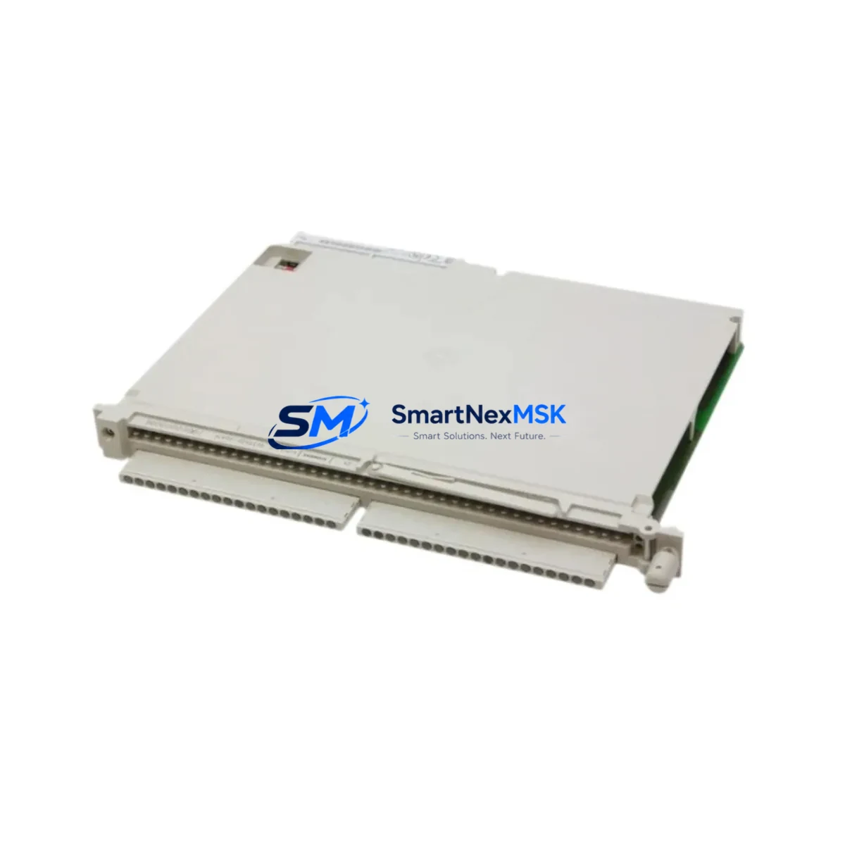
Siemens 6ES5420-4UA14 Maintenance-Ready Spare for SIMATIC S5 Automation
The Siemens 6ES5420-4UA14 is a 32-channel 24V DC digital input module designed for the SIMATIC S5 programmable logic controller platform. As legacy S5 systems continue to operate across manufacturing plants, water treatment facilities, chemical processing lines, and power distribution substations, maintaining a verified stock of original spare modules is critical to minimizing unplanned downtime and protecting production continuity. This module serves as a direct, plug-compatible replacement for failed or degraded units within S5-115U, S5-135U, and S5-155U rack configurations, enabling maintenance engineers to execute rapid board-swap procedures without requiring software reconfiguration or hardware adaptation.
For procurement engineers managing MRO budgets and spare parts inventories, the 6ES5420-4UA14 represents a high-priority line item. Its 32-channel density means a single module failure can take offline an entire field I/O group — sensors, limit switches, proximity detectors, or pushbutton interlocks — simultaneously. Stocking at least one verified replacement unit per control cabinet is a widely adopted best practice in facilities running continuous or semi-continuous processes where scheduled maintenance windows are infrequent.
Each unit supplied by SMARTNEXMSK undergoes pre-shipment functional verification, including channel-level input response testing and backplane connector inspection, and is covered by a 12-month warranty from the date of delivery.
Spare Maintenance Table
| Part Number | 6ES5420-4UA14 |
| Brand | Siemens |
| Series | SIMATIC S5 |
| Module Type | Digital Input Module (DI) |
| Number of Channels | 32 channels |
| Input Voltage | 24V DC |
| Signal Logic | Positive switching (source type) |
| Compatible Racks | S5-115U, S5-135U, S5-155U |
| Backplane Interface | S5 parallel bus (721-pin edge connector) |
| Input Isolation | Optocoupler-isolated per channel group |
| Operating Temperature | 0°C to +60°C |
| Mounting | Direct rack insertion, no tools required |
| Origin | Germany |
| Condition | Original, tested, ready to ship |
| Warranty | 12 months from delivery date |
| Compatibility Verified | Yes — drop-in replacement for 6ES5420-4UA14 |
| Maintenance Recommendation | Inspect terminal block wiring and backplane slot contacts during installation; clean with isopropyl alcohol if oxidation is present |
Maintenance Planning for Continuous Operation
When replacing the 6ES5420-4UA14 in a SIMATIC S5 control cabinet, a thorough maintenance engineer will treat the event as an opportunity to inspect the surrounding electrical environment rather than performing a simple board swap. The 24V DC field supply feeding the input module should be verified at the terminal strip — voltage sag below 20V DC or ripple exceeding 5% can cause intermittent input misreads that mimic module failure. The 6ES5951-7NA00 or equivalent S5 power supply module should be checked for output stability and capacitor aging, particularly in systems older than ten years.
The 40-pin front connector and its associated terminal block wiring should be inspected for loose crimps, corroded ferrules, or reversed polarity on inductive sensor circuits. If the cabinet also houses a 6ES5430-4UA12 digital output module sharing the same field wiring duct, inspect those output channels simultaneously — output-side faults can back-feed into input circuits under certain wiring fault conditions.
For systems using a 6ES5095-8MA02 or 6ES5095-8MB02 central processing unit, confirm that the CPU’s I/O address assignment for the replaced module slot remains intact after power cycling. In older S5 configurations, address switches on the module itself or rack slot assignments in the CPU’s memory may need to be verified against the original system documentation.
If the control cabinet includes a 6ES5700-series communications processor for PROFIBUS or serial data exchange, verify that the communication cycle is not disrupted by the module replacement — some S5 CPUs require a warm restart to re-initialize the I/O bus after a module change. Additionally, inspect any 6ES5482-series analog input modules in adjacent slots, as analog signal quality can be affected by ground loop changes introduced during digital module replacement.
For facilities maintaining older S5 systems alongside newer S7-300 or S7-400 infrastructure, it is advisable to cross-reference the 6ES5420-4UA14 spare with equivalent S7-compatible digital input modules such as the 6ES7321-1BL00-0AA0, which may be relevant if a phased migration is planned. Keeping both generations of spares in the MRO inventory ensures flexibility during transition periods.
Terminal blocks, DIN rail mounting hardware, and 24V DC fuse holders (typically 2A slow-blow per input group) should also be included in the cabinet inspection checklist. Signal isolators or surge protection devices installed on long cable runs from field sensors to the input module should be tested for proper clamping voltage and continuity.
Site Replacement Workflow
Step 1 — Isolate and document: Before removing the failed 6ES5420-4UA14, photograph the front connector wiring and record the module’s slot position and address configuration. Power down the affected rack section using the appropriate circuit breaker or isolator, not the main cabinet disconnect, to avoid disrupting other active modules.
Step 2 — Remove and inspect: Disconnect the 40-pin front connector by releasing the locking lever. Slide the module out of the rack slot. Inspect the backplane connector pins for bent contacts or carbon deposits. Clean the slot with dry compressed air before inserting the replacement unit.
Step 3 — Install replacement: Insert the new 6ES5420-4UA14 firmly into the rack slot until the backplane connector is fully seated. Reconnect the front connector and verify that all terminal screws are torqued to specification (typically 0.5–0.8 Nm for S5 terminal blocks).
Step 4 — Power-up and verify: Restore power to the rack section. Observe the module’s LED status indicators — all 32 input LEDs should reflect the current field signal states within 2–3 seconds of power-up. Use the S5 programming device (PG 740, PG 760, or STEP 5 software on a compatible PC) to force-test individual input channels if field conditions permit.
Step 5 — Return to service: Confirm with the control room operator that all process signals are reading correctly before releasing the system to automatic operation. Log the replacement in the maintenance management system with the module serial number, installation date, and technician ID.
This workflow is applicable whether replacing a failed unit during an emergency callout or executing a planned swap during a scheduled shutdown. The 6ES5420-4UA14 supplied by SMARTNEXMSK is tested prior to shipment, reducing the risk of installing a defective spare and extending the downtime event.
Spare Parts Support FAQ
Q1: Is the 6ES5420-4UA14 still available as a new original part, or is it a refurbished unit?
SMARTNEXMSK supplies original Siemens 6ES5420-4UA14 modules sourced from verified industrial channels. Each unit is inspected and functionally tested before shipment. Where new-old-stock units are available, they are prioritized; all units are clearly described by condition at the time of order confirmation.
Q2: How do I verify compatibility with my existing S5 rack before ordering?
The 6ES5420-4UA14 is compatible with all standard S5 expansion racks using the parallel backplane bus, including the EU183U, EU185U, and EU187U expansion units. Confirm your rack model and slot availability before ordering. If you are unsure, provide your rack model and CPU type to [email protected] and our technical team will confirm compatibility within one business day.
Q3: What does the 12-month warranty cover, and how is a warranty claim processed?
The 12-month warranty covers functional failure under normal operating conditions — correct supply voltage, within-spec operating temperature, and proper installation per Siemens documentation. Physical damage caused by overvoltage, incorrect wiring, or mechanical impact is excluded. To initiate a warranty claim, contact [email protected] with your order number, a description of the fault, and photos of the installed module and wiring. Replacement or refund is processed within 5 business days of claim approval.
Q4: Can SMARTNEXMSK supply multiple units for a planned maintenance stock program?
Yes. SMARTNEXMSK supports bulk spare parts procurement for facilities maintaining multiple S5 systems. Volume pricing is available for orders of 3 or more units of the same part number. Long-term supply agreements with reserved stock allocation can be arranged for critical infrastructure operators. Contact [email protected] or call +86 18259474341 to discuss your inventory requirements.
© 2026 SMARTNEXMSK. All rights reserved.
Original Source: https://smartnexmsk.com
Contact: [email protected] | +86 18259474341



