
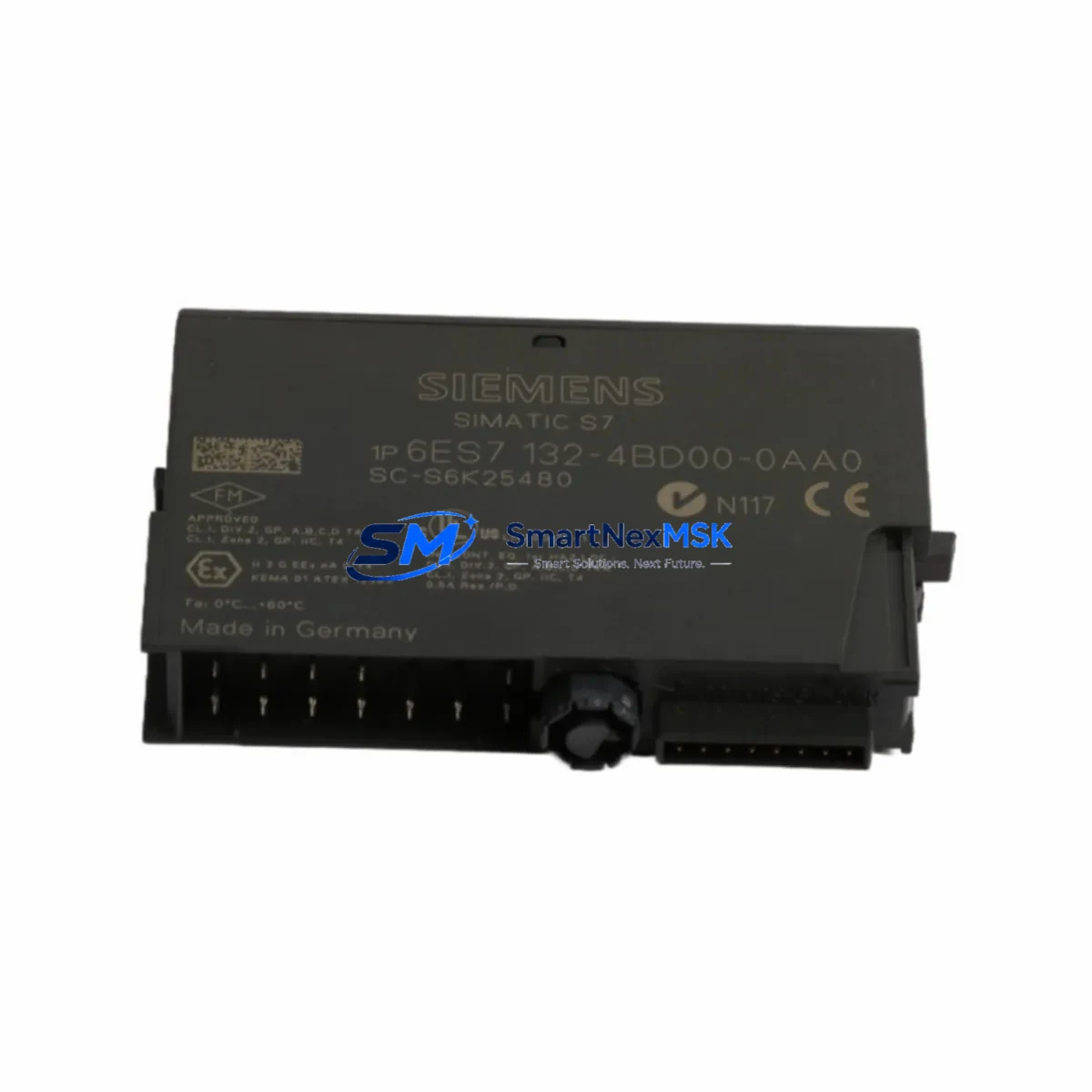
Siemens 6ES7132-4BD31-0AA0 Retrofit-Ready Digital Output for ET 200S Control Systems
The Siemens 6ES7132-4BD31-0AA0 is a 2-channel 24 VDC / 0.5 A digital output module designed for the ET 200S distributed I/O system. As legacy automation lines face increasing pressure to modernize, this module serves as a verified drop-in replacement for discontinued or end-of-life output modules within the ET 200S platform. Whether you are restoring a failed control cabinet, expanding an existing rack, or migrating from an older SIMATIC S7-300 distributed I/O architecture, the 6ES7132-4BD31-0AA0 provides a reliable, specification-matched solution with minimal re-engineering effort.
This module slots directly into the ET 200S terminal module — specifically the TM-E15S24-A1 or TM-E15C24-A1 — without requiring backplane rewiring. The 24 VDC supply rail is shared across the power module (PM-E 24VDC, 6ES7138-4CA01-0AA0), and output channel addressing is automatically assigned by the IM 151-1 interface module based on slot position. Engineers replacing a failed unit should verify that the IM 151-1 firmware version supports the module type code, as older interface module revisions may require a firmware update before the new output module is recognized on the PROFIBUS DP or PROFINET network.
Upgrade Compatibility Table
| Parameter | Details |
|---|---|
| Module Type | 2DO DC 24V / 0.5A Digital Output |
| Compatible Series | Siemens ET 200S Distributed I/O |
| Terminal Module | TM-E15S24-A1 / TM-E15C24-A1 (existing wiring retained) |
| Interface Module | IM 151-1 Standard / IM 151-3 PN (PROFIBUS DP / PROFINET) |
| Power Module | PM-E 24VDC (6ES7138-4CA01-0AA0) — shared rail, no change required |
| Communication Protocol | PROFIBUS DP / PROFINET (via IM 151-x) |
| Replacement Scope | Direct slot-for-slot replacement; no backplane rewiring |
| Address Assignment | Automatic via IM 151-1 slot position |
| Commissioning Tool | STEP 7 v5.x / TIA Portal V13 and above |
| Firmware Dependency | Verify IM 151-1 firmware supports module type code |
| Warranty | 12 Months — tested before shipment |
Retrofit Planning for Existing Automation Systems
Successful retrofit of the 6ES7132-4BD31-0AA0 into an operating production line requires a structured pre-replacement checklist. Begin by documenting the current slot assignment within the ET 200S rack. The IM 151-1 interface module maintains a hardware configuration table that maps each slot to a process image address range. If the replacement module is inserted into the same slot as the failed unit, the STEP 7 or TIA Portal hardware configuration does not need to be modified — the CPU (such as a SIMATIC S7-315-2 DP or S7-317-2 PN/DP) will resume normal scan cycle operation after the IM 151-1 re-establishes the PROFIBUS DP connection.
For sites running older SIMATIC S7-300 CPUs with distributed I/O over PROFIBUS DP, confirm that the GSD file for the ET 200S station is current. Outdated GSD files may cause the CPU to flag a configuration mismatch fault (OB 86 or OB 122) even when the physical module is correctly installed. In TIA Portal environments, the hardware catalog entry for the 6ES7132-4BD31-0AA0 should be verified against the installed module’s order number and firmware version.
When the control cabinet also contains a SIMATIC HMI panel — such as a TP700 Comfort or KTP900 Basic — connected via PROFINET, verify that the HMI screen tags referencing the output channel addresses remain valid after the swap. If the original module was mapped to a specific output byte in the process image, and the replacement module occupies the same slot, tag addresses are preserved without HMI project modification.
For systems incorporating a CP 343-1 or CP 343-1 Advanced communications processor for Ethernet connectivity, no changes to the CP configuration are required when replacing a digital output module within the ET 200S station. Similarly, if the rack includes an FM 350-1 counter module or an SM 322 digital output module in an adjacent S7-300 rack, those modules are unaffected by the ET 200S swap.
Power budget verification is essential before installation. The ET 200S power module (PM-E 24VDC) supplies the 24 VDC load current for all electronic modules on its segment. The 6ES7132-4BD31-0AA0 draws a maximum of 10 mA from the backplane bus and up to 1 A from the 24 VDC load supply (2 × 0.5 A channels at full load). Confirm that the PM-E module’s rated current capacity is not exceeded when all output channels in the segment are simultaneously energized.
Terminal wiring on the TM-E15S24-A1 terminal module is retained during module replacement — the electronic module clips onto the terminal module without disturbing field wiring. Label each terminal before removal as a precaution, and photograph the wiring layout for documentation. After insertion of the replacement module, perform a point-to-point output test using the STEP 7 Variable Monitor or TIA Portal Watch Table to confirm each channel activates the correct field device before returning the line to automatic mode.
Downtime Control During System Migration
Minimizing unplanned downtime during a digital output module replacement on an active ET 200S station requires preparation before the maintenance window opens. The recommended approach is to pre-configure a spare 6ES7132-4BD31-0AA0 module offline, verify its order number against the hardware configuration, and stage it at the control cabinet before initiating the shutdown sequence.
In PROFIBUS DP networks, the CPU enters STOP mode or triggers OB 86 (rack failure) when the ET 200S station loses communication. To prevent cascading faults in interconnected stations, isolate the affected ET 200S station in the STEP 7 hardware configuration by temporarily setting the station to “deactivated” before the physical swap, if the process permits a controlled shutdown. This prevents the CPU from generating persistent fault messages that could affect HMI alarm logs or historian records.
For PROFINET-based systems using the IM 151-3 PN interface module, the device replacement without exchangeable medium (PROFIsafe or standard) feature allows the new module to be recognized automatically after insertion, provided the device name and IP address assignment are retained. This eliminates the need for a laptop connection at the cabinet during the swap, reducing the time the line is offline.
After module insertion and power restoration, monitor the IM 151-1 or IM 151-3 PN diagnostic LEDs (SF, BF, ON) to confirm successful re-integration. A solid green ON LED with no SF or BF fault indicates the module is recognized and communicating. Return the CPU to RUN mode only after all output channels have been verified through the Watch Table or a manual jog sequence. Document the replacement date, module serial number, and test results in the maintenance log to support the 12-month warranty claim if required.
Retrofit Support FAQ
Q1: Is the 6ES7132-4BD31-0AA0 a direct replacement for the 6ES7132-4BD30-0AA0?
Yes. The 6ES7132-4BD31-0AA0 is the current-generation successor to the 6ES7132-4BD30-0AA0. Both modules are 2DO 24VDC / 0.5A digital output modules for the ET 200S platform and are slot-compatible. No hardware configuration change is required in STEP 7 or TIA Portal when replacing the older variant with the 6ES7132-4BD31-0AA0 in the same slot position.
Q2: What commissioning steps are required after installation?
After inserting the module into the TM-E terminal module and restoring power, use STEP 7 Variable Monitor or TIA Portal Watch Table to force each output channel ON and verify the corresponding field device activates correctly. Check the IM 151-1 diagnostic buffer for any configuration mismatch faults. If a fault is present, confirm the hardware configuration in STEP 7 matches the installed module order number and download the updated configuration to the CPU.
Q3: Will existing field wiring need to be changed?
No. The TM-E15S24-A1 or TM-E15C24-A1 terminal module retains all field wiring when the electronic module is removed and replaced. The 6ES7132-4BD31-0AA0 clips onto the terminal module without disturbing terminal connections. Verify terminal tightness and insulation condition as a standard maintenance practice, but no rewiring is required for a like-for-like replacement.
Q4: What does the 12-month warranty cover?
All units are function-tested prior to shipment. The 12-month warranty covers manufacturing defects and functional failures under normal operating conditions (24 VDC supply, rated load current, ambient temperature within specification). Warranty claims require the original order reference and a description of the fault condition. Units damaged by overvoltage, reverse polarity, or installation error are not covered under the standard warranty terms.
© 2026 SMARTNEXMSK. All rights reserved.
Original Source: https://smartnexmsk.com
Contact: [email protected] | +86 18259474341



