Siemens 6ES7134-4JB50-0AB0 Retrofit-Ready Analog Input for ET 200S Control Systems
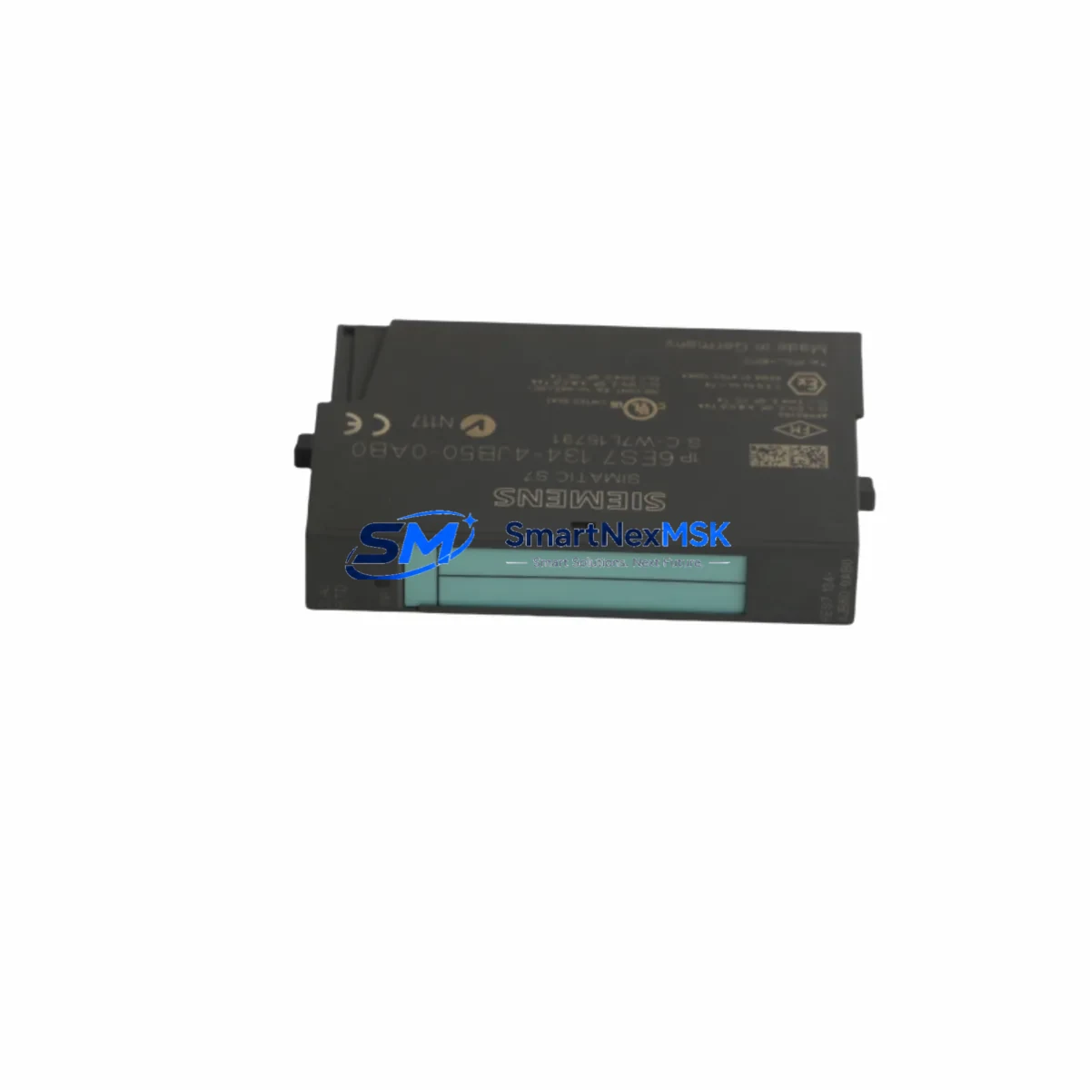
The Siemens 6ES7134-4JB50-0AB0 is a 2-channel analog input module designed for the ET 200S distributed I/O platform. As legacy automation lines age and original spare parts become increasingly difficult to source, this module serves as a critical retrofit component for engineers tasked with modernizing or sustaining existing Siemens S7-300 and S7-400 control architectures. Whether you are replacing a failed unit on a running production line, upgrading a control cabinet to extend its operational life, or migrating from an older Profibus-based system toward a more current Profinet infrastructure, the 6ES7134-4JB50-0AB0 provides a reliable, drop-in-compatible solution backed by a 12-month warranty.
This module accepts standard analog signal types including voltage and current inputs, making it suitable for interfacing with a wide range of field instruments such as pressure transmitters, temperature sensors, and flow meters. Its compact form factor fits directly into the ET 200S terminal module carrier, eliminating the need for panel redesign or additional wiring adapters during a retrofit. Engineers replacing discontinued predecessors such as the 6ES7134-4FB01-0AB0 or 6ES7134-4GB01-0AB0 will find that the 6ES7134-4JB50-0AB0 maintains backward-compatible terminal assignments, significantly reducing rewiring time during scheduled maintenance windows.
Upgrade Compatibility Table
| Parameter | Details |
|---|---|
| SKU / Part Number | 6ES7134-4JB50-0AB0 |
| Series / Platform | Siemens ET 200S Distributed I/O |
| Compatible Controllers | S7-300, S7-400, S7-1500 (via IM interface) |
| Communication Protocol | Profibus DP / Profinet IO |
| Analog Input Channels | 2 AI (voltage / current selectable) |
| Terminal Module | Compatible with TM-E15S24-A1 / TM-E15S24-01 |
| Backplane Interface | ET 200S standard backplane bus |
| Installation Requirement | DIN rail mount via ET 200S terminal module |
| Replacement Compatibility | 6ES7134-4FB01-0AB0, 6ES7134-4GB01-0AB0 |
| Commissioning Note | Module address set via IM 151 interface module; verify GSD/GSDML file version |
| Warranty | 12 Months |
Retrofit Planning for Existing Automation Systems
Successful integration of the 6ES7134-4JB50-0AB0 into an existing control system requires careful pre-retrofit planning. Before removing the failed or obsolete module, engineers should document the current terminal wiring layout using the existing panel drawings or perform a live trace if drawings are unavailable. The ET 200S system uses a modular terminal module concept, meaning the TM-E15S24-A1 terminal module remains in place while only the electronics module is swapped — a significant advantage for minimizing downtime.
Power budget verification is an essential step. The ET 200S power supply module, such as the 6ES7138-4CA01-0AA0 PM-E DC24V power module, must be confirmed to have sufficient current capacity to support the replacement module alongside all other installed I/O modules on the same segment. Overloading the power segment is a common cause of intermittent faults after a retrofit.
For systems communicating over Profibus DP, the interface module 6ES7151-1AA06-0AB0 IM 151-1 manages module addressing and bus participation. When replacing an analog input module, the module slot address must match the original configuration stored in the S7 hardware configuration (HW Config) in STEP 7 or TIA Portal. If the GSD file version differs between the old and new module, a hardware reconfiguration and download may be required — plan for this in your maintenance window.
In systems that have already migrated to Profinet, the 6ES7151-3BA23-0AB0 IM 151-3 PN interface module handles Profinet IO communication. Verify that the GSDML file for the 6ES7134-4JB50-0AB0 is imported into TIA Portal and that the device name and IP address assignment are consistent with the existing network topology. Mismatched device names are a frequent source of commissioning delays.
For control cabinets that include HMI panels such as the Siemens TP700 Comfort or KTP900 Basic, confirm that any analog value display tags linked to the replaced module’s I/O addresses remain valid after the swap. Tag address offsets can shift if the hardware configuration is reorganized during the retrofit. A pre-commissioning simulation using WinCC or TIA Portal’s integrated HMI simulation tool is recommended before going live.
Where the retrofit involves I/O expansion — for example, adding additional analog channels alongside the replacement — consider pairing the 6ES7134-4JB50-0AB0 with a 6ES7135-4GB01-0AB0 2AO analog output module to complete a closed-loop control upgrade within the same ET 200S station. This approach avoids the need for a separate remote I/O station and keeps the control architecture compact.
All replacement modules are tested prior to shipment. Each unit undergoes functional verification including channel-level signal accuracy checks, bus communication handshake testing, and power consumption measurement. Units are shipped with original-style packaging to prevent ESD damage during transit.
Downtime Control During System Migration
Minimizing unplanned downtime is the primary concern for any retrofit involving live production equipment. The ET 200S modular architecture is specifically designed to support hot-swap of electronics modules without disturbing terminal wiring — a feature that makes the 6ES7134-4JB50-0AB0 replacement particularly efficient when the terminal module is already installed and wired.
Before initiating the swap, place the affected PLC CPU in STOP mode or isolate the relevant Profibus/Profinet segment if a partial stop is operationally acceptable. Export and archive the current STEP 7 or TIA Portal project, including the hardware configuration, to ensure a known-good restore point is available. If the system uses a Siemens S7-300 CPU 315-2 DP or similar controller with a memory card, verify that the project is saved to the card and not only to the CPU’s internal RAM.
After installing the replacement module, perform a controlled power-up sequence: restore power to the ET 200S station, confirm the module’s RUN LED status, and check the diagnostic buffer in the CPU for any configuration mismatch faults. If the system uses a 6ES7972-0CB20-0XA0 PC adapter USB or 6GK1571-0BA00-0AA0 PROFIBUS connector for programming access, ensure the programming cable is connected and the online monitoring function is active during first power-up to catch any address conflicts immediately.
For systems where a full CPU stop is not acceptable, coordinate with the process control team to place the affected control loop in manual mode at the DCS or SCADA level before the swap. This preserves field control continuity while the module is exchanged, and allows the analog input values to be re-verified against field instrument readings before returning the loop to automatic control.
Retrofit Support FAQ
Q1: Is the 6ES7134-4JB50-0AB0 a direct replacement for the 6ES7134-4FB01-0AB0?
A: Yes, the 6ES7134-4JB50-0AB0 is functionally compatible with the 6ES7134-4FB01-0AB0 and installs into the same TM-E terminal module. Terminal wiring does not need to be changed. A hardware configuration update in STEP 7 or TIA Portal may be required if the GSD/GSDML file version differs.
Q2: What wiring checks should be performed before powering up the replacement module?
A: Verify that the signal type (voltage or current) selected via the module’s parameter settings matches the field instrument output. Confirm that the 24 VDC supply to the terminal module is within specification (20.4–28.8 VDC). Check that shield connections are properly grounded at the cabinet entry point to avoid noise interference on the analog channels.
Q3: How is the module address configured in the ET 200S station?
A: The module address is determined by its physical slot position within the ET 200S station and is managed by the IM 151 or IM 151-3 PN interface module. The address is defined in the hardware configuration in STEP 7 or TIA Portal and downloaded to the CPU. No manual DIP switch setting is required on the 6ES7134-4JB50-0AB0 itself.
Q4: What does the 12-month warranty cover?
A: The 12-month warranty covers manufacturing defects and functional failures under normal operating conditions. Each unit is tested before shipment. Warranty claims are supported via email at sales@smartnexmsk.com or by phone at +86 18259474341. Replacement or repair is arranged promptly to minimize impact on your production schedule.
© 2026 SMARTNEXMSK. All rights reserved.
Original Source: https://smartnexmsk.com
Contact: sales@smartnexmsk.com | +86 18259474341