
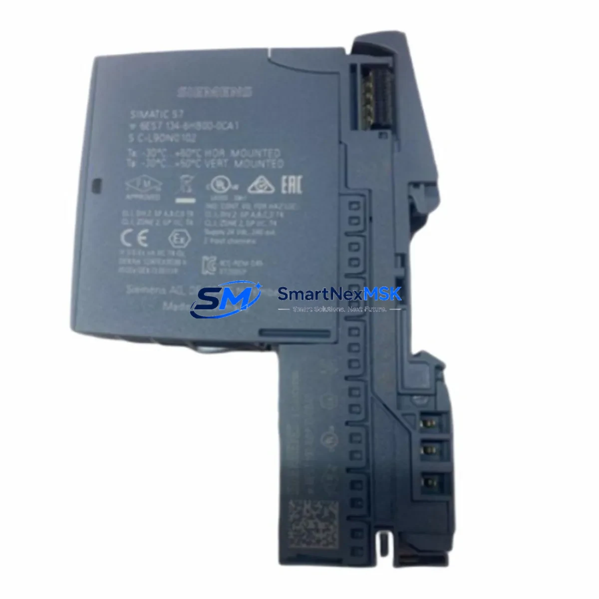
Siemens 6ES7134-6HB00-0CA1 Retrofit-Ready Digital Input Module for ET 200SP Control Systems
The Siemens 6ES7134-6HB00-0CA1 is an 8-channel, 24 VDC digital input module designed for the ET 200SP distributed I/O platform. As legacy automation lines age and original Siemens spare parts become increasingly difficult to source, this module serves as a verified retrofit-ready replacement for facilities running SIMATIC S7-1500, S7-1200, or older S7-300 control architectures that have migrated field I/O to the ET 200SP backplane. Whether you are recovering from an unplanned failure, executing a planned control cabinet upgrade, or expanding I/O capacity on an existing rack, the 6ES7134-6HB00-0CA1 delivers the electrical and firmware compatibility required for a smooth, low-risk transition.
Upgrade Compatibility Table
| Parameter | 6ES7134-6HB00-0CA1 (This Module) | Retrofit Notes |
|---|---|---|
| Channel Count | 8 × Digital Input | Direct replacement for 8DI predecessors on ET 200SP rack |
| Input Voltage | 24 VDC (IEC Type 1/3) | Verify field wiring voltage before installation |
| Backplane Interface | ET 200SP BaseUnit BU15-P16+A0+2D (6ES7193-6BP20-0DA0) | BaseUnit must be pre-installed; module snaps in without tools |
| Communication Compatibility | PROFINET IO via IM 155-6 PN interface module | Compatible with IM 155-6 PN ST (6ES7155-6AU01-0BN0) and HF variants |
| Installation Requirement | 35 mm DIN rail, ET 200SP system | No additional mounting hardware required |
| Replacement Recommendation | Replaces 6ES7131-6BH01-0BA0 (8DI predecessor) | Confirm GSD/GSDML file version in TIA Portal project |
| Commissioning Focus | Module address assignment via TIA Portal V15+ | Re-download hardware configuration after slot substitution |
| Warranty | 12-Month Warranty — covers manufacturing defects and functional failure under normal operating conditions | |
Retrofit Planning for Existing Automation Systems
A successful retrofit of the 6ES7134-6HB00-0CA1 begins well before the module arrives on site. Engineers should audit the existing ET 200SP rack layout, confirming that the correct BaseUnit BU15-P16+A0+2D is already installed in the target slot. If the rack was originally populated with an older 8DI module such as the 6ES7131-6BH01-0BA0, the BaseUnit is typically compatible, but the GSDML device description file in the TIA Portal project must be updated to reflect the new module type before downloading the revised hardware configuration.
Power budget verification is a critical pre-installation step. The ET 200SP system distributes 24 VDC load power across the backplane via the Power Module PM-E 24VDC (6ES7138-6CB01-0BA0). Before adding or replacing I/O modules, confirm that the total current draw of all installed modules — including any 6ES7134-6GD00-0CA1 analog input modules, 6ES7132-6BH01-0BA0 digital output modules, and communication-intensive modules such as the 6ES7137-6AA00-0BA0 IO-Link master — does not exceed the power module’s rated output. Exceeding the backplane power budget is a common cause of intermittent faults during retrofit commissioning.
Terminal wiring should be documented before removal of the old module. The ET 200SP BaseUnit uses push-in terminals, and field cables connected to the original module remain in place when the I/O module is swapped. However, engineers should verify terminal labeling against the original panel drawings, particularly on lines that share common potential with adjacent 6ES7193-6BP20-0DA0 BaseUnits. Any discrepancy between the field wiring diagram and the TIA Portal symbol table should be resolved before the new module is powered on.
For systems where the ET 200SP rack communicates upstream to a SIMATIC S7-1500 CPU 1515-2 PN or a CPU 1516-3 PN/DP, the PROFINET device name and IP address of the IM 155-6 PN interface module must remain unchanged during the module swap. The interface module retains its network identity independently of the I/O modules installed in the rack, so communication continuity is maintained as long as the interface module itself is not replaced. If the project also includes an HMI TP700 Comfort or similar panel connected via PROFINET, verify that the HMI tag table references the correct I/O addresses after the hardware configuration download, as slot renumbering can shift absolute I/O addresses in older TIA Portal projects.
For facilities migrating from a legacy SIMATIC S7-300 platform with ET 200M distributed I/O, the transition to ET 200SP requires a full hardware redesign in TIA Portal. The 6ES7134-6HB00-0CA1 is native to the ET 200SP ecosystem and is not backward-compatible with ET 200M IM 153 interface modules. In this migration scenario, the programming cable 6ES7972-0CB20-0XA0 (PC Adapter USB A2) may still be required to access legacy S7-300 CPUs during the parallel-run commissioning phase before full cutover.
Downtime Control During System Migration
Minimizing production downtime during a digital input module replacement requires a structured approach to pre-staging, program backup, and cutover sequencing. Before any physical work begins, use TIA Portal to perform a full project backup, including the hardware configuration, program blocks, and HMI project. Store the backup on a network drive independent of the engineering workstation to ensure recovery capability if the commissioning download encounters an unexpected fault.
Where process conditions allow, schedule the module swap during a planned maintenance window rather than responding reactively to a module failure. Pre-configure the replacement 6ES7134-6HB00-0CA1 in the TIA Portal offline project, compile the hardware configuration, and verify that no errors are reported before arriving on site. This eliminates the most common source of extended downtime — discovering configuration mismatches only after the old module has been removed.
During the physical swap, the ET 200SP system can be powered down at the rack level by removing the PM-E 24VDC power module rather than shutting down the entire control cabinet, provided that the upstream CPU is placed in STOP mode first. This approach preserves power to other sections of the control panel and reduces the risk of unintended actuator movement during the maintenance window. After the new module is seated and the power module is reinstalled, perform a controlled CPU restart and monitor the diagnostic buffer in TIA Portal for any module fault entries before releasing the line back to production.
Original program logic does not require modification when replacing a like-for-like 8DI module in the same slot. The I/O addresses, symbol assignments, and interlock logic in the S7-1500 program remain valid as long as the hardware configuration download is completed successfully. If the slot position changes during the retrofit — for example, when consolidating a partially populated rack — update the I/O address assignments in the TIA Portal symbol table and perform a full program consistency check before downloading.
Retrofit Support FAQ
Q1: Is the 6ES7134-6HB00-0CA1 a direct drop-in replacement for the 6ES7131-6BH01-0BA0?
A: Functionally yes — both are 8-channel 24 VDC digital input modules for the ET 200SP platform and use the same BaseUnit. However, the GSDML file version differs between module generations. You must update the hardware configuration in TIA Portal and perform a new download to the IM 155-6 PN interface module before the replacement module will be recognized correctly by the CPU.
Q2: What commissioning steps are required after installation?
A: After seating the module, power on the ET 200SP rack and open TIA Portal. Navigate to the Online & Diagnostics view for the IM 155-6 PN interface module and confirm that the new module appears without fault indicators. Download the updated hardware configuration if prompted. Verify that all 8 input channels report the correct signal states against known field conditions before releasing the system to automatic operation.
Q3: Can I use this module in a system that also has analog input modules on the same ET 200SP rack?
A: Yes. The ET 200SP backplane supports mixed I/O configurations. The 6ES7134-6HB00-0CA1 can be installed in the same rack alongside analog input modules such as the 6ES7134-6GD00-0CA1 (4AI ±10V) and analog output modules, provided the total backplane power budget is not exceeded. Confirm the power calculation in TIA Portal’s hardware configuration before finalizing the rack layout.
Q4: What does the 12-month warranty cover, and how is it claimed?
A: The 12-month warranty covers manufacturing defects and functional failure under normal operating conditions, including electrical faults, communication errors attributable to the module, and physical defects present at the time of delivery. It does not cover damage resulting from incorrect installation, overvoltage, or environmental conditions outside the module’s rated specifications. To initiate a warranty claim, contact our sales team with the order reference number, a description of the fault, and diagnostic screenshots from TIA Portal if available. Replacement or repair will be arranged within the warranty period at no additional cost.
© 2026 SMARTNEXMSK. All rights reserved.
Original Source: https://smartnexmsk.com
Contact: [email protected] | +86 18259474341



