
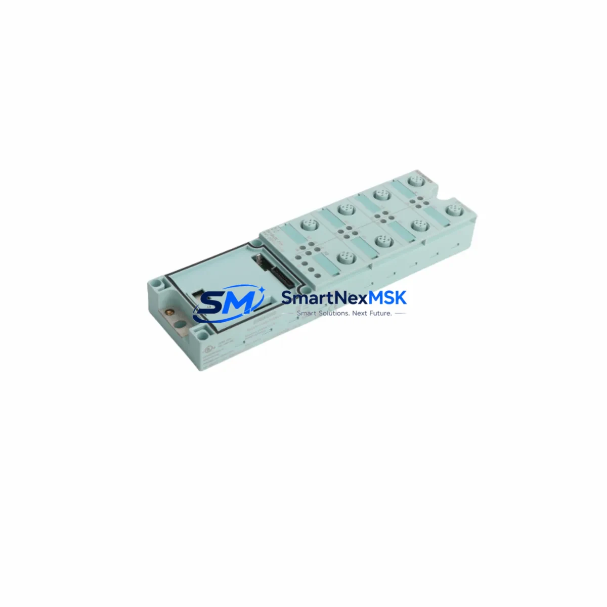
Siemens 6ES7141-3BH00-0XA0 Spare for ET 200S Automation: Spare Parts Replacement & Industrial Downtime Risk Control
The Siemens 6ES7141-3BH00-0XA0 is an 8-channel 24 VDC digital input module designed for the SIMATIC ET 200S distributed I/O system. As a maintenance-ready spare, it plays a critical role in keeping production lines operational during scheduled maintenance windows, emergency fault isolation, and long-term system life extension programs. For maintenance engineers managing aging SIMATIC S7-300 or S7-400 control architectures with ET 200S field stations, holding a verified replacement unit of the 6ES7141-3BH00-0XA0 in the spare parts cabinet is a fundamental risk-reduction strategy.
This module interfaces directly with the ET 200S interface module — typically the IM 151-1 or IM 151-3 PN — and occupies a standard terminal module slot on the ET 200S rail assembly. Its 8 digital inputs accept 24 VDC signals from field sensors, proximity switches, pushbuttons, and limit switches. When a channel fails or the module develops a fault LED condition, the entire associated input group may go offline, triggering process alarms or forcing a controlled shutdown. Having a pre-tested 6ES7141-3BH00-0XA0 on hand allows the maintenance team to execute a hot-swap replacement within minutes rather than waiting days for emergency procurement.
From a procurement engineering perspective, the 6ES7141-3BH00-0XA0 is a long-running catalog item within the SIMATIC ET 200S family, but Siemens has progressively migrated customers toward the ET 200SP platform. This makes sourcing original, tested spare units increasingly important for facilities that are not yet ready to undertake a full platform migration. Stocking this module as part of a structured spare parts inventory — alongside the corresponding terminal module TM-E15S24-01 and the ET 200S power module PM-E 24VDC — ensures that a single component failure does not cascade into an extended production halt.
Spare Maintenance Table
| Parameter | Specification |
|---|---|
| Part Number / SKU | 6ES7141-3BH00-0XA0 |
| Series / Platform | SIMATIC ET 200S Distributed I/O |
| Module Type | 8-Channel Digital Input Module |
| Input Voltage | 24 VDC (IEC 61131-2 Type 1/3) |
| Number of Inputs | 8 DI |
| Input Current (per channel) | Approx. 4 mA at 24 VDC |
| Signal Delay | Configurable: 0.1 ms / 0.5 ms / 3 ms / 15 ms |
| Compatible Interface Modules | IM 151-1 Standard, IM 151-1 FO, IM 151-3 PN |
| Terminal Module Required | TM-E15S24-01 (sold separately) |
| Backplane Bus | ET 200S internal bus (SIMATIC) |
| Degree of Protection | IP20 |
| Operating Temperature | 0 °C to +60 °C |
| Dimensions (W × H × D) | 15 mm × 81 mm × 52 mm (approx.) |
| Weight | Approx. 220 g (with terminal module) |
| Country of Origin | Germany |
| Compatibility | SIMATIC S7-300, S7-400, ET 200S stations |
| Condition | Original, new or tested-refurbished |
| Pre-shipment Testing | Function-tested before dispatch |
| Warranty | 12 Months |
Maintenance Planning for Continuous Operation
Effective maintenance planning for an ET 200S station running the 6ES7141-3BH00-0XA0 requires a holistic view of the entire I/O cabinet and field wiring loop. When replacing this digital input module during a planned shutdown or emergency callout, maintenance engineers should simultaneously inspect and verify the following associated components to prevent repeat failures and ensure system integrity:
The ET 200S Power Module PM-E 24VDC (6ES7138-4CA01-0AA0) supplies 24 VDC to the electronic and load circuits of the I/O modules on the same rail segment. A degraded PM-E can cause intermittent input faults that mimic a failed DI module — always verify output voltage stability under load before condemning the 6ES7141-3BH00-0XA0. Similarly, the IM 151-1 Interface Module governs all communication between the ET 200S station and the PROFIBUS DP or PROFINET network; a firmware mismatch or hardware fault on the IM can cause the entire station — including all installed 6ES7141-3BH00-0XA0 modules — to drop offline.
Field wiring integrity is equally critical. The TM-E15S24-01 Terminal Module that the 6ES7141-3BH00-0XA0 snaps onto must be inspected for cracked housing, corroded contacts, or loose screw terminals. A faulty terminal module will cause persistent channel faults even after the electronic module is replaced. Check all 24 VDC field sensor cables for insulation damage, especially in high-vibration or high-temperature environments. Proximity switches, inductive sensors, and photoelectric sensors connected to the input channels should be tested for correct switching voltage and leakage current compliance with IEC 61131-2 Type 1/3 input specifications.
For stations with mixed I/O, also inspect adjacent digital output modules (e.g., 6ES7132-4BB01-0AA0) and analog input modules (e.g., 6ES7134-4FB01-0AB0) on the same ET 200S rail. Shared power segments mean that a short circuit or overload on an output module can affect the supply rail feeding the 6ES7141-3BH00-0XA0. If the station includes PROFIBUS DP connectors or PROFINET patch cables, verify connector seating and cable continuity — communication errors at the network layer are frequently misdiagnosed as I/O module hardware faults.
Where signal isolation is required between field devices and the PLC input circuit, signal isolators or signal conditioners in the 24 VDC input loop should be checked for correct output levels. In older installations, fuse terminal blocks (e.g., Phoenix Contact or Weidmüller fused terminals) protecting individual input channels may have blown fuses that prevent signal transmission — a common oversight during fault isolation. Finally, if the ET 200S station is part of a larger SIMATIC S7-300 or S7-400 control cabinet, verify the CPU’s I/O configuration in STEP 7 or TIA Portal to confirm the hardware configuration matches the physical slot assignment of the replacement 6ES7141-3BH00-0XA0 module.
Site Replacement Workflow
Replacing the 6ES7141-3BH00-0XA0 in the field is a straightforward procedure when the correct spare is available and the replacement workflow is followed systematically. The module uses a tool-free snap-on design with the TM-E15S24-01 terminal module, meaning the electronic module can be swapped without disturbing field wiring — a significant advantage for minimizing downtime during emergency replacements.
Step 1 — Isolate and document: Before removal, record the current diagnostic state of the module via STEP 7 or TIA Portal online diagnostics. Note any active channel faults, SF/BF LED states, and the last known process values. This documentation supports root-cause analysis after the replacement is complete.
Step 2 — Power-down or hot-swap assessment: The ET 200S supports module replacement under power (MRP) for standard modules including the 6ES7141-3BH00-0XA0, provided the interface module and CPU support this feature. Confirm MRSP capability in the station configuration before attempting a live swap. If in doubt, de-energize the affected power segment via the PM-E module’s load voltage switch.
Step 3 — Module removal and inspection: Unlatch the 6ES7141-3BH00-0XA0 from the terminal module by pressing the release lever and sliding the electronic module upward. Inspect the terminal module contacts and the backplane bus connector for contamination or mechanical damage before installing the replacement unit.
Step 4 — Install and verify: Snap the new 6ES7141-3BH00-0XA0 onto the terminal module. Power up the segment and observe the RUN/SF/BF LEDs. A solid green RUN LED with no SF or BF indication confirms successful module recognition. Verify all 8 input channels via the online diagnostics view in TIA Portal or STEP 7 by actuating each connected field device.
Step 5 — System compatibility confirmation: If the replacement module has a different firmware version, perform a GSD/GSDML file update in the engineering tool if required. Confirm that the hardware configuration download is not necessary for standard module replacement — in most ET 200S configurations, the replacement module is automatically recognized without a new configuration download.
This workflow applies equally to planned maintenance replacements and emergency fault recovery scenarios, and is designed to keep total replacement time under 30 minutes for a trained maintenance technician.
Spare Parts Support FAQ
Q1: Is the 6ES7141-3BH00-0XA0 still available as a new original spare, or is it discontinued?
The 6ES7141-3BH00-0XA0 is a mature product within the SIMATIC ET 200S family. While Siemens has introduced the ET 200SP as the successor platform, the 6ES7141-3BH00-0XA0 remains available as an original spare through authorized industrial distributors and specialist spare parts suppliers. We maintain stock of original and tested-refurbished units to support facilities that are not yet migrating to ET 200SP. All units are function-tested before shipment and covered by a 12-month warranty.
Q2: How do I verify compatibility before installing a replacement 6ES7141-3BH00-0XA0 in my ET 200S station?
Compatibility verification involves three checks: (1) confirm the terminal module type — the 6ES7141-3BH00-0XA0 requires a TM-E15S24-01 or equivalent E-type terminal module; (2) verify the interface module firmware supports the module type — check the IM 151-1 or IM 151-3 PN product information page for compatible electronic module lists; (3) confirm the hardware configuration in STEP 7 or TIA Portal matches the physical slot. In standard ET 200S configurations, a direct replacement with the same order number requires no configuration changes.
Q3: What pre-shipment testing is performed on the 6ES7141-3BH00-0XA0 before delivery?
Every 6ES7141-3BH00-0XA0 unit we supply undergoes a functional test that includes power-on verification, channel-by-channel input signal testing at 24 VDC, LED status confirmation, and backplane bus communication check. Units that do not pass all test criteria are not dispatched. A test report is available upon request for quality-critical applications. All units ship with a 12-month warranty covering manufacturing defects and functional failures under normal operating conditions.
Q4: What is the recommended spare parts inventory strategy for ET 200S digital input modules?
For facilities with multiple ET 200S stations, we recommend maintaining a minimum of one 6ES7141-3BH00-0XA0 spare per 5–8 installed units, with a minimum of one unit per site regardless of installed quantity. High-criticality lines — where a single I/O station failure causes a full production stop — should maintain two spare units. Pair the DI module spare with a spare TM-E15S24-01 terminal module and a spare PM-E 24VDC power module to cover the most common failure scenarios. Long-term supply continuity is supported through our stocking program, which provides priority access to replacement units for registered customers.
© 2026 SMARTNEXMSK. All rights reserved.
Original Source: https://smartnexmsk.com
Contact: [email protected] | +86 18259474341



