
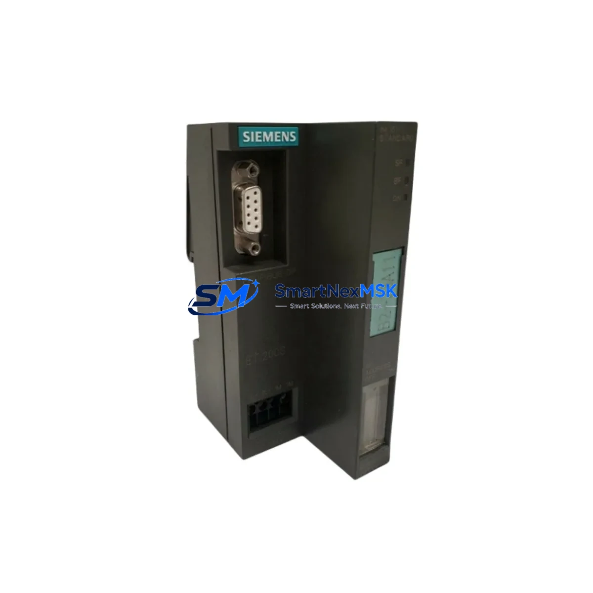
Siemens 6ES7151-1AA03-0AB0 Maintenance-Ready Spare for ET 200S Automation
The Siemens 6ES7151-1AA03-0AB0 is the IM 151-1 Standard interface module for the SIMATIC ET 200S distributed I/O system, communicating via PROFIBUS DP at up to 12 Mbit/s. As a maintenance-ready original spare part, it is the critical link between the PROFIBUS DP master — typically a SIMATIC S7-300 or S7-400 CPU — and the ET 200S terminal modules installed in field control cabinets. When this interface module fails or degrades, the entire ET 200S station drops off the PROFIBUS network, causing immediate process interruption. Holding a verified replacement in your spare parts inventory is the single most effective measure to minimize unplanned downtime in PROFIBUS-based automation systems.
This unit is sourced as an original Siemens component, inspected and function-tested prior to shipment, and covered by a 12-month warranty. It is suitable for direct replacement in existing ET 200S stations without hardware reconfiguration, provided the STEP 7 or TIA Portal project retains the original hardware configuration.
Spare Maintenance Table
| Parameter | Specification |
|---|---|
| Part Number / SKU | 6ES7151-1AA03-0AB0 |
| Module Type | IM 151-1 Standard Interface Module |
| Series / System | SIMATIC ET 200S |
| Communication Protocol | PROFIBUS DP (Slave) |
| Baud Rate | 9.6 kbit/s – 12 Mbit/s (auto-detect) |
| Supply Voltage | DC 24 V (via power module PM-E or PM-D) |
| Max. I/O Modules per Station | Up to 63 terminal modules |
| Diagnostic Functions | PROFIBUS DP diagnostics, LED status indicators |
| Mounting | DIN rail, ET 200S terminal module base |
| Operating Temperature | 0 °C to +60 °C |
| Protection Class | IP20 |
| Country of Origin | Germany |
| Compatibility | SIMATIC S7-300, S7-400, S7-1500 (via PROFIBUS DP master) |
| Engineering Software | STEP 7 V5.x, TIA Portal V13 and above |
| Warranty | 12 Months |
| Condition | Original, tested before shipment |
Maintenance Planning for Continuous Operation
When planning a scheduled inspection or emergency replacement of the 6ES7151-1AA03-0AB0, maintenance engineers should treat the entire ET 200S station as a system — not just the interface module in isolation. The IM 151-1 draws its 24 VDC supply through the station’s power module; a degraded 6ES7138-4CA01-0AA0 PM-E DC 24V power module can cause intermittent resets that are misdiagnosed as interface module faults. Always verify supply voltage at the PM-E terminals before condemning the IM 151-1.
The PROFIBUS DP cable and connector quality directly affects station stability. Inspect the PROFIBUS DP bus connector (6ES7972-0BA52-0XA0) for pin corrosion, damaged termination resistors, and correct cable shielding. A marginal bus connector can cause sporadic communication errors that worsen as the IM 151-1 ages. Replacing the interface module without addressing a faulty connector will not resolve the underlying fault.
Within the ET 200S station, digital and analog terminal modules such as the 6ES7131-4BF00-0AA0 4DI DC 24V and 6ES7134-4FB01-0AB0 2AI U analog input module should be inspected for terminal corrosion, blown fuses, and LED fault indicators during the same maintenance window. I/O module faults are frequently masked by a failed interface module because the entire station goes offline together.
For motor starter applications within the same ET 200S station, the 6ES7138-4DF01-0AB0 PM-D power module for motor starters and associated 3RK1301 motor starter modules should be checked for overload trip history and contact wear. These components share the same PROFIBUS station address and will all appear offline when the IM 151-1 fails.
On the PROFIBUS master side, verify that the SIMATIC S7-300 CP 342-5 communications processor (6GK7342-5DA02-0XE0) or the onboard PROFIBUS DP port of the CPU module shows no hardware fault LEDs. A failing CP module can generate bus errors that accelerate wear on interface modules across multiple ET 200S stations.
For facilities running mixed PROFIBUS and PROFINET architectures, the 6ES7151-3BA23-0AB0 IM 151-3 PN interface module is the PROFINET-capable successor and should be evaluated during long-term system modernization planning. Stocking both variants ensures coverage across legacy and upgraded stations.
Finally, the 6ES7193-4CA40-0AA0 terminal module TM-E15S26-A1 base units that the IM 151-1 plugs into should be inspected for cracked housings and damaged locking levers. A damaged terminal module base can cause poor electrical contact even with a new interface module installed.
Site Replacement Workflow
Step 1 — Isolate and document: Before removal, record the PROFIBUS DP station address set on the IM 151-1 rotary switches (tens and units digits). Photograph the wiring and LED status. In STEP 7 or TIA Portal, note the hardware configuration slot assignments for all I/O modules in the station.
Step 2 — De-energize safely: Switch off the 24 VDC supply to the ET 200S station via the upstream circuit breaker or the PM-E power module switch. Confirm zero voltage at the IM 151-1 supply terminals before proceeding.
Step 3 — Remove the failed module: Unlock the IM 151-1 from its terminal module base by pressing the release lever and sliding the module upward. The terminal module base (6ES7193-4CA40-0AA0) remains on the DIN rail — no rewiring is required.
Step 4 — Install the replacement 6ES7151-1AA03-0AB0: Set the PROFIBUS DP station address on the rotary switches to match the original setting. Slide the new module onto the terminal module base until it clicks into place.
Step 5 — Re-energize and verify: Restore 24 VDC supply. The IM 151-1 SF (System Fault) LED should extinguish within a few seconds as the module establishes PROFIBUS DP communication. Confirm all I/O module LEDs return to normal operating state. In STEP 7 or TIA Portal online view, verify the ET 200S station shows no hardware faults.
Step 6 — Functional test: Cycle the controlled process through its normal operating sequence to confirm all I/O signals are correctly mapped. Document the replacement in the maintenance log with date, technician name, and new module serial number.
This replacement procedure requires no changes to the PLC program or hardware configuration, provided the replacement module is the same order number (6ES7151-1AA03-0AB0) and the PROFIBUS station address is correctly set. Total on-site replacement time for a trained technician is typically under 15 minutes, making rapid spare availability the primary factor in minimizing downtime.
Spare Parts Support FAQ
Q1: Is the 6ES7151-1AA03-0AB0 still available as a new original part, or is it discontinued?
The 6ES7151-1AA03-0AB0 has reached end-of-life in Siemens’ standard product portfolio, but original stock remains available through authorized industrial spare parts suppliers. For systems that cannot be migrated to PROFINET in the short term, maintaining a stock of 1–2 units per ET 200S station is strongly recommended. Long-term supply is supported through specialist distributors who hold certified original inventory.
Q2: How do I verify compatibility before installation?
Confirm the PROFIBUS DP station address range supported by your master CPU, the maximum number of I/O modules in the station (up to 63 for IM 151-1 Standard), and that your STEP 7 or TIA Portal hardware configuration uses the 6ES7151-1AA03-0AB0 GSD file. No firmware update is required for direct replacement. If your project was configured with an earlier hardware revision, verify in the hardware catalog that the -0AB0 suffix is compatible with your GSD version.
Q3: What pre-shipment testing is performed on this spare part?
Each 6ES7151-1AA03-0AB0 unit is function-tested prior to shipment to verify PROFIBUS DP communication establishment, LED indicator operation, and supply voltage acceptance within specification. Units are shipped in anti-static packaging with individual serial number documentation. A 12-month warranty covers manufacturing defects and functional failures under normal operating conditions.
Q4: What is the recommended spare parts inventory strategy for ET 200S systems?
For production-critical ET 200S installations, maintain at minimum one IM 151-1 interface module per 3–5 stations, one PM-E power module per station, and a set of the most-used I/O terminal modules (4DI, 2DO, 2AI) per control cabinet. For facilities with more than 10 ET 200S stations, a centralized spare parts cabinet with labeled, tested modules reduces mean time to repair (MTTR) to under 30 minutes for most station-level faults. Annual inspection and rotation of stored spares is recommended to prevent storage-related degradation.
© 2026 SMARTNEXMSK. All rights reserved.
Original Source: https://smartnexmsk.com
Contact: [email protected] | +86 18259474341



