
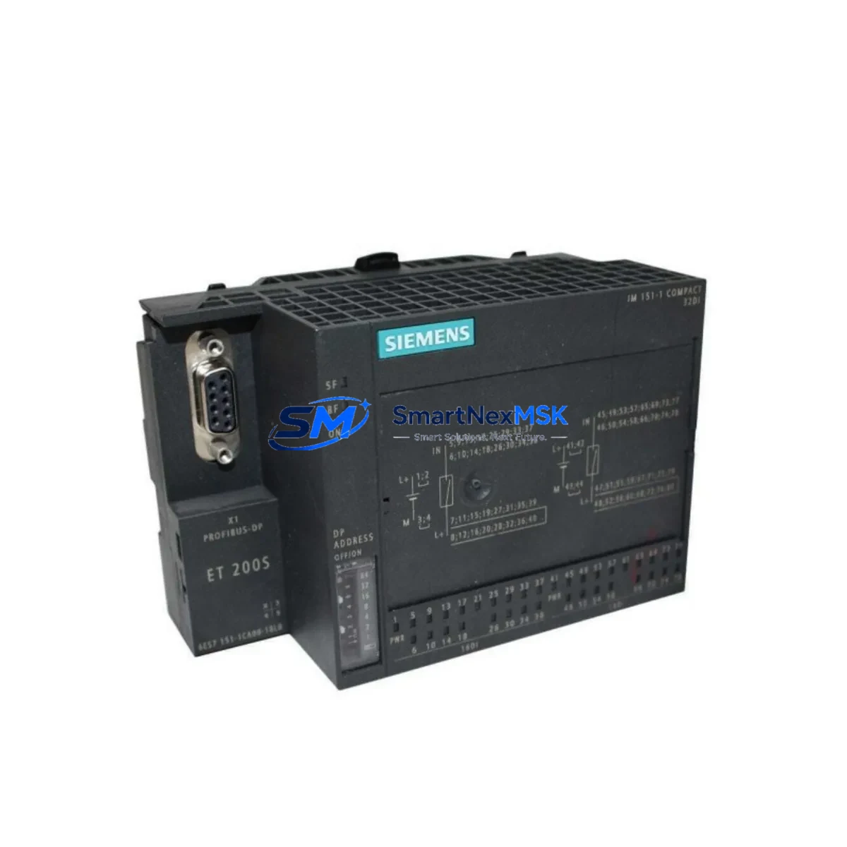
Siemens 6ES7151-1CA00-1BL0 Maintenance-Ready Spare ET200S Automation
The Siemens 6ES7151-1CA00-1BL0 is a PROFIBUS DP slave interface module for the ET200S distributed I/O system, designed to integrate seamlessly into Siemens S7-300 and S7-400 PLC architectures. As a critical communication gateway between the field-level I/O station and the PROFIBUS DP master, this interface module governs data exchange, station addressing, and diagnostic reporting across the entire ET200S rack. When this module fails or degrades, the entire distributed I/O station goes offline — making rapid spare parts availability a non-negotiable element of any industrial maintenance strategy.
At SMARTNEXMSK, every 6ES7151-1CA00-1BL0 unit is sourced as an original Siemens component, individually tested for communication integrity and electrical performance before dispatch. Our inventory is maintained specifically to support maintenance engineers and procurement teams who cannot afford extended lead times on critical automation spares. With a 12-month warranty and pre-shipment functional verification, this module is ready for immediate site installation upon arrival.
Spare Maintenance Table
| Parameter | Specification |
|---|---|
| Part Number | 6ES7151-1CA00-1BL0 |
| Brand | Siemens |
| Series | ET200S / SIMATIC S7-300 |
| Module Type | PROFIBUS DP Slave Interface Module |
| Communication Protocol | PROFIBUS DP (up to 12 Mbit/s) |
| Supply Voltage | 24 V DC (via backplane bus) |
| Station Address Range | 1–125 (configurable via DIP switch) |
| Max. I/O Modules per Station | Up to 63 modules |
| Diagnostic Functions | Station diagnostics, module diagnostics, channel diagnostics |
| Operating Temperature | 0 °C to +60 °C |
| Protection Class | IP20 |
| Mounting | DIN rail, ET200S terminal module |
| Country of Origin | Germany |
| Compatibility | S7-300, S7-400, PROFIBUS DP masters, TIA Portal / STEP 7 |
| Condition | Original, New / Tested Surplus |
| Warranty | 12 Months |
| Pre-Shipment Test | Communication integrity, power-on, diagnostic response |
Maintenance Planning for Continuous Operation
When a 6ES7151-1CA00-1BL0 interface module is flagged for replacement during a planned shutdown or emergency callout, experienced maintenance engineers know that the interface module is rarely the only component requiring attention. A thorough inspection of the surrounding ET200S station and PROFIBUS segment is essential to prevent repeat failures and ensure a clean restart.
Begin by verifying the 24 V DC power supply module feeding the ET200S rack — voltage sags or ripple on the supply rail are a common root cause of interface module communication faults. Inspect the PM-E power module (e.g., 6ES7138-4CA01-0AA0) for signs of overheating or output instability. Next, audit the PROFIBUS DP cable and connectors: damaged shielding, incorrect termination resistors, or loose 9-pin D-sub connectors at the interface module port will cause intermittent communication errors that persist even after module replacement.
Check all digital input modules (e.g., 6ES7131-4BF00-0AA0) and digital output modules (e.g., 6ES7132-4BF00-0AA0) seated in the ET200S rack. A failed I/O module can generate diagnostic alarms that are misattributed to the interface module. Similarly, inspect analog input modules (e.g., 6ES7134-4FB01-0AB0) for signal drift or channel faults, particularly in high-vibration or thermally stressed environments.
For stations integrated into safety-rated circuits, verify the status of any F-I/O modules or safety relay modules in the rack. Review the terminal modules (TM-E, TM-P series) for corrosion or loose wiring at the field connection points — these are frequently overlooked during routine inspections but are a significant source of intermittent faults. If the ET200S station communicates upstream to a Siemens S7-300 CPU (e.g., CPU 315-2 DP, 6ES7315-2AH14-0AB0), confirm that the PROFIBUS master configuration in STEP 7 or TIA Portal still matches the physical station address set on the replacement module’s DIP switches.
Where the control cabinet also houses SIMATIC HMI panels (e.g., KTP700 Basic or TP1200 Comfort) connected to the same PROFIBUS or MPI network, verify that HMI communication parameters are unaffected by the module swap. Finally, check any signal isolators or surge protection devices on the PROFIBUS line — these components absorb transient damage that may have contributed to the original module failure and should be replaced proactively as part of the corrective maintenance scope.
Site Replacement Workflow
Replacing the 6ES7151-1CA00-1BL0 on a live ET200S station requires a structured approach to minimize downtime and avoid configuration errors. Follow this workflow for a controlled, efficient swap:
1. Pre-Replacement Preparation: Download and archive the current STEP 7 or TIA Portal project, including the hardware configuration for the affected ET200S station. Note the PROFIBUS station address currently set on the DIP switches of the outgoing module — this must be replicated exactly on the replacement unit before installation.
2. Safe Isolation: Place the PROFIBUS DP master in STOP mode or isolate the affected station using the master’s diagnostic tools. De-energize the ET200S rack via the upstream power supply. Do not remove the interface module under live bus conditions.
3. Module Removal and Inspection: Remove the faulty 6ES7151-1CA00-1BL0 from its terminal module. Inspect the terminal module contacts and the backplane bus connector for damage. If the terminal module shows signs of arcing or deformation, replace it concurrently — reusing a damaged terminal module with a new interface module will cause premature failure.
4. Replacement Module Configuration: Set the PROFIBUS station address on the new module’s DIP switches to match the archived value. Verify the address against the hardware configuration in STEP 7 / TIA Portal before proceeding.
5. Installation and Restart: Seat the replacement module firmly onto the terminal module. Re-energize the rack and bring the PROFIBUS master back to RUN mode. Monitor the diagnostic LEDs on the interface module — the BF (Bus Fault) LED should extinguish within seconds of successful PROFIBUS synchronization. Confirm all I/O modules in the station report healthy status in the PLC diagnostic buffer.
6. Post-Replacement Verification: Perform a full I/O force test on critical channels before returning the system to production. Document the replacement in the maintenance log, including the new module’s serial number and the date of installation.
Spare Parts Support FAQ
Q1: Is the 6ES7151-1CA00-1BL0 compatible with both STEP 7 Classic and TIA Portal projects?
Yes. The 6ES7151-1CA00-1BL0 is supported in both STEP 7 V5.x (Classic) and TIA Portal environments. The module’s GSD file is available from Siemens and must be installed in the engineering software if not already present. No firmware update is required for standard replacement in an existing configuration.
Q2: What is your pre-shipment testing procedure for this module?
Every unit undergoes a power-on functional test, PROFIBUS communication response check, and diagnostic LED verification before dispatch. Modules that fail any stage of testing are quarantined and not shipped. A test report is available upon request for quality-critical procurement.
Q3: Can this module replace older variants such as the 6ES7151-1AA00-0AB0 or 6ES7151-1BA00-0AB0?
Direct hardware substitution depends on the specific firmware revision and terminal module compatibility of your existing ET200S station. We recommend confirming the hardware revision of your current installation against the Siemens compatibility matrix before ordering. Our technical team can assist with compatibility verification prior to purchase.
Q4: What does the 12-month warranty cover, and what is the RMA process?
The 12-month warranty covers manufacturing defects and functional failures under normal operating conditions. If a module fails within the warranty period, contact our sales team at [email protected] with the order number and fault description. We will arrange a replacement dispatch or full refund within agreed lead times. Warranty does not cover damage resulting from incorrect installation, overvoltage events, or unauthorized modification.
© 2026 SMARTNEXMSK. All rights reserved.
Original Source: https://smartnexmsk.com
Contact: [email protected] | +86 18259474341



