
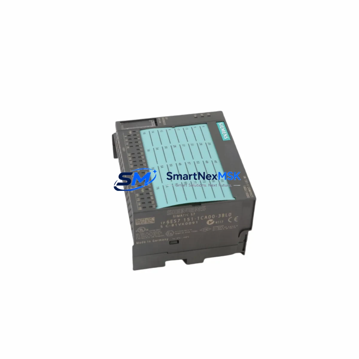
Siemens 6ES7151-1CA00-3BL0 Retrofit-Ready IM151-1 for ET 200S Control Systems
The Siemens 6ES7151-1CA00-3BL0 is the IM151-1 Standard Interface Module for the ET 200S distributed I/O system, communicating over PROFIBUS DP at up to 12 Mbit/s. As legacy automation lines age and original Siemens spare parts become increasingly scarce, this module has become a critical retrofit component for engineers tasked with keeping ET 200S stations operational without a full system overhaul. Whether you are replacing a failed unit on an active production line, upgrading an aging control cabinet, or migrating from an earlier IM151 variant, the 6ES7151-1CA00-3BL0 provides a verified drop-in solution that preserves your existing rack architecture, terminal wiring, and STEP 7 program logic.
This module mounts directly onto the ET 200S terminal module TM-IM/IM and supports the full range of ET 200S I/O modules — including digital input/output modules such as the 6ES7131-4BF00-0AA0 and 6ES7132-4BF00-0AA0, analog modules, and technology modules — without requiring hardware reconfiguration of the downstream I/O tier. The integrated PROFIBUS DP interface connects directly to the DP master, typically a CP 342-5 communications processor or the onboard DP port of an S7-300 CPU 315-2 DP, maintaining the existing network topology and GSD-based device configuration.
Upgrade Compatibility Table
| Parameter | 6ES7151-1CA00-3BL0 (IM151-1 Standard) | Notes / Retrofit Guidance |
|---|---|---|
| Communication Protocol | PROFIBUS DP (slave) | Compatible with all DP masters; GSD file required for HW Config |
| Max PROFIBUS Baud Rate | 12 Mbit/s | Match baud rate setting in STEP 7 HW Config |
| Power Supply Voltage | DC 24 V (via terminal module) | Verify PS 307 or equivalent supply capacity ≥ 2 A |
| Max I/O Modules per Station | 63 modules | Recount modules if expanding I/O during retrofit |
| Backplane Interface | ET 200S internal bus via TM-IM/IM | No backplane rewiring required for like-for-like swap |
| Installation | DIN rail, snap-on terminal module | Confirm TM-IM/IM terminal module is undamaged before swap |
| Replaces / Compatible With | 6ES7151-1AA00-0AB0, 6ES7151-1BA00-0AB0 | Earlier IM151-1 variants; verify firmware and GSD version |
| STEP 7 / TIA Portal | STEP 7 V5.x; TIA Portal via legacy library | Re-import GSD if upgrading from earlier IM151 variant |
| Commissioning Tool | SIMATIC Manager / TIA Portal | Use online diagnostics to verify DP address after swap |
| Warranty | 12-Month Warranty — tested and verified before shipment | |
Retrofit Planning for Existing Automation Systems
A successful retrofit of the 6ES7151-1CA00-3BL0 begins well before the module arrives on site. The first step is a thorough audit of the existing ET 200S station: document the current PROFIBUS DP node address set on the rotary switches of the outgoing IM151-1, record the exact I/O module sequence in the rack, and photograph all terminal wiring on the downstream TM-E15S24-01 or TM-E30S44-01 terminal modules. This documentation becomes the reference baseline for post-swap verification and significantly reduces commissioning time.
Power budget verification is equally critical. The ET 200S station draws its 24 VDC supply through the power module — typically a 6ES7138-4CA01-0AA0 PM-E DC24V — and the IM151-1 itself consumes current from this rail. When adding I/O modules during the same retrofit window, recalculate the total current draw against the rated output of the installed power module to avoid nuisance tripping or undervoltage faults after restart.
For stations that include 6ES7138-4HA00-0AB0 F-PM-E fail-safe power modules or safety-rated I/O such as the 6ES7136-6RA00-0BF0 F-RO relay output module, the retrofit scope must include a review of the safety program in STEP 7 Safety or TIA Portal Safety Advanced. Safety-relevant parameters — including F-Address, F-Monitoring Time, and CRC — must be re-validated after any interface module replacement, and a proof test may be required under your site’s functional safety management plan.
Communication link integrity should be confirmed at the PROFIBUS segment level. Check the bus termination resistors at both ends of the DP segment — typically built into the PROFIBUS connector 6ES7972-0BB52-0XA0 — and verify that the cable shielding is properly grounded at the control cabinet entry point. If the retrofit coincides with a migration from PROFIBUS DP to PROFINET, consider whether the station warrants replacement with an ET 200S PN variant using the 6ES7151-3AA23-0AB0 IM151-3 PN interface module, which supports PROFINET IO and enables integration into a TIA Portal-managed network without replacing the downstream I/O modules.
For sites running older S7-400 controllers with IM 460-3 or IM 461-3 expansion interfaces, the ET 200S station connected via PROFIBUS DP remains fully compatible with the 6ES7151-1CA00-3BL0, and no changes to the S7-400 hardware configuration are required beyond a re-download of the modified HW Config after updating the DP slave properties.
Downtime Control During System Migration
Minimizing unplanned downtime during an IM151-1 swap requires a structured hot-swap preparation protocol. Begin by placing the DP master in STOP mode from the SIMATIC Manager or TIA Portal online view — do not simply cut power to the ET 200S station, as an uncontrolled power loss may corrupt the module’s internal parameter set and trigger a longer recovery sequence on restart.
Before removing the outgoing 6ES7151-1CA00-3BL0 (or its predecessor), use the STEP 7 online diagnostics to capture the current module status, I/O data, and any pending fault codes. Export the hardware configuration as a backup archive. This archive allows you to restore the exact DP slave configuration — including the node address, baud rate, and I/O module assignment — to the replacement module without re-entering parameters manually, protecting the integrity of the original program logic and HMI variable mappings.
Once the replacement module is seated on the TM-IM/IM terminal module and the PROFIBUS connector is reattached, set the rotary address switches to match the documented node address before applying power. Power up the ET 200S station and observe the BF (Bus Fault) and SF (System Fault) LEDs on the IM151-1 front panel. A steady green RUN LED with no BF or SF indication confirms successful DP parameterization. Transition the DP master back to RUN mode and verify that all I/O signals — including analog inputs from any installed 6ES7134-4FB01-0AB0 analog input modules — are reading correctly in the HMI or SCADA system before releasing the line to production.
For facilities with strict change-management requirements, pre-stage the replacement module in the workshop, configure and test it on a bench ET 200S rack with a spare SIMATIC S7-300 CPU and a PC Adapter USB A2 6ES7972-0CB20-0XA0 programming cable, and obtain sign-off on the bench test report before scheduling the live swap. This approach compresses the on-site intervention window to under 30 minutes for a straightforward like-for-like replacement.
Retrofit Support FAQ
Q1: Is the 6ES7151-1CA00-3BL0 a direct replacement for the 6ES7151-1AA00-0AB0 and 6ES7151-1BA00-0AB0?
A: Yes, the IM151-1 Standard (6ES7151-1CA00-3BL0) is the current-generation successor to earlier IM151-1 variants. The mechanical form factor, TM-IM/IM terminal module interface, and PROFIBUS DP slave functionality are identical. After swapping, re-import the GSD file in STEP 7 HW Config if the firmware version differs, and re-download the hardware configuration to the DP master to ensure correct parameterization.
Q2: What wiring changes are required when replacing the interface module?
A: For a like-for-like IM151-1 replacement, no terminal wiring changes are required. All field wiring remains on the downstream terminal modules (TM-E, TM-M series). Only the PROFIBUS DP connector needs to be transferred from the outgoing module to the replacement. Confirm that the connector’s terminating resistor switch position matches the original setting before reconnecting.
Q3: How is compatibility with the existing STEP 7 program verified before going live?
A: Use STEP 7 online diagnostics to compare the hardware configuration stored in the CPU against the physical station after the swap. If the GSD version of the replacement module matches the original, the CPU will recognize the station without a re-download. If a GSD update is required, re-download the HW Config to the DP master only — the user program in the CPU does not need to be modified.
Q4: What does the 12-month warranty cover, and how is the module tested before shipment?
A: Every 6ES7151-1CA00-3BL0 unit is powered on and functionally tested prior to shipment, including PROFIBUS DP communication verification and LED status confirmation. The 12-month warranty covers manufacturing defects and functional failures under normal operating conditions. Units are shipped in anti-static packaging with full documentation. Contact our technical team for warranty claims or pre-shipment test reports.
© 2026 SMARTNEXMSK. All rights reserved.
Original Source: https://smartnexmsk.com
Contact: [email protected] | +86 18259474341



