
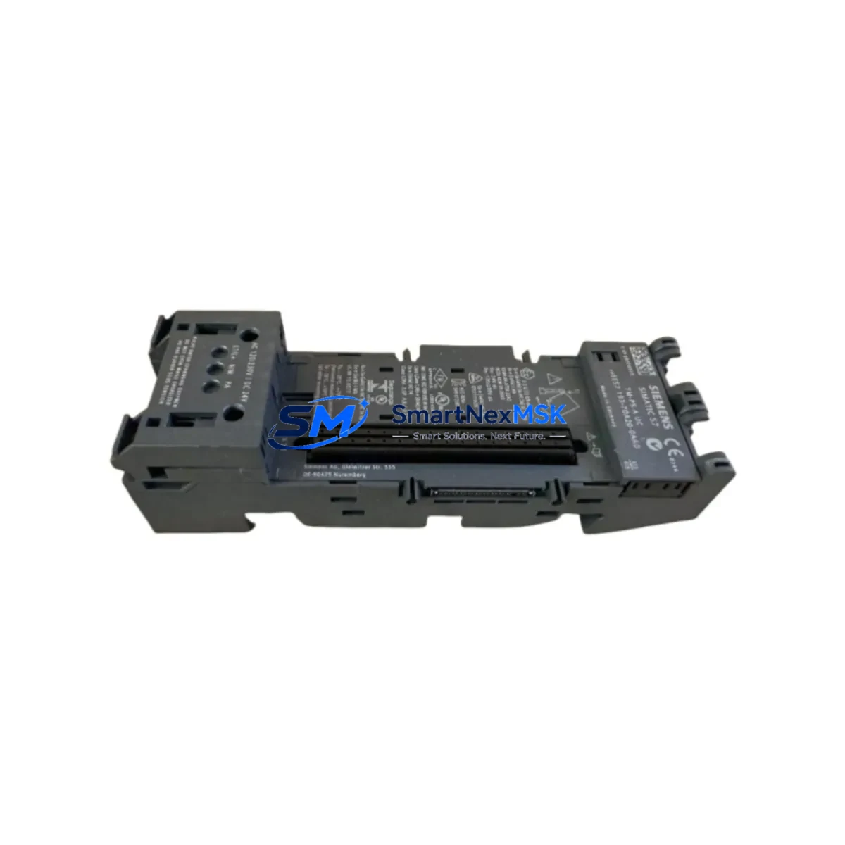
Siemens 6ES7193-7DA20-0AA0 Retrofit-Ready BaseUnit for ET 200SP Control Systems
The Siemens 6ES7193-7DA20-0AA0 is a BU15-P16+A0+2D BaseUnit designed for the ET 200SP distributed I/O system. As a retrofit-ready replacement module, it enables seamless integration into existing SIMATIC S7-1200 and S7-1500 control architectures without requiring rack redesign or PLC program restructuring. Whether you are replacing a failed unit, upgrading an aging control cabinet, or migrating from an earlier ET 200S platform, this BaseUnit provides the terminal density, backplane connectivity, and PROFINET compatibility required for modern industrial automation environments.
Each unit shipped by SMARTNEXMSK undergoes pre-delivery functional verification, including backplane bus continuity checks, terminal block seating confirmation, and visual inspection against Siemens factory specifications. All units are covered by a 12-month warranty from the date of shipment.
Upgrade Compatibility Table
| Parameter | Details |
|---|---|
| SKU / Part Number | 6ES7193-7DA20-0AA0 |
| Module Type | BU15-P16+A0+2D BaseUnit |
| Compatible Series | ET 200SP (SIMATIC S7-1200 / S7-1500) |
| Backplane Interface | ET 200SP internal bus (left/right connector) |
| Terminal Capacity | 15 terminals (P16 push-in type) |
| Communication Protocol | PROFINET IO (via IM 155-6 interface module) |
| Replaces / Upgrades From | ET 200S BaseUnits, earlier ET 200SP BU variants |
| Installation Type | DIN rail mount, tool-free module insertion |
| Commissioning Notes | Module address auto-assigned via STEP 7 / TIA Portal slot configuration |
| Warranty | 12 months from shipment date |
Retrofit Planning for Existing Automation Systems
When integrating the 6ES7193-7DA20-0AA0 into an existing control system, engineers must begin with a thorough review of the current cabinet layout and backplane bus topology. In a typical ET 200SP station, the BaseUnit sits between the IM 155-6 PN ST interface module (which handles PROFINET communication upstream to the S7-1500 CPU) and the adjacent I/O modules such as the 6ES7131-6BF01-0AA0 digital input module or the 6ES7132-6BF01-0AA0 digital output module. Confirming that the replacement BaseUnit’s bus connector orientation matches the existing station layout is the first critical step — misaligned left/right bus connectors are a common source of commissioning errors during retrofit projects.
Power budget verification is equally important. The ET 200SP station draws load current through the 6ES7138-6AA01-0AA0 PM-E power module, and adding or replacing BaseUnits may shift the total current draw. Engineers should cross-reference the power module’s rated output against the aggregate consumption of all I/O modules in the station, particularly when the retrofit involves adding new 6ES7134-6GD01-0BA1 analog input modules or 6ES7135-6GB01-0BA1 analog output modules alongside the replacement BaseUnit.
For systems migrating from the older ET 200S platform, the wiring adaptation is more involved. ET 200S used screw-type terminals on separate terminal modules, whereas the ET 200SP BaseUnit uses push-in spring-clamp terminals. Field wiring cross-sections must be verified — the 6ES7193-7DA20-0AA0 accepts conductors from 0.14 mm² to 1.5 mm² (solid or stranded). In many retrofit scenarios, existing cable looms can be re-terminated directly without replacing the cable itself, significantly reducing downtime.
Communication link continuity must also be validated. If the existing station uses a 6ES7155-6AU01-0BN0 IM 155-6 PN HF interface module with Media Redundancy Protocol (MRP) enabled, the PROFINET ring topology must remain intact during the swap. Coordinating with the network administrator to temporarily disable MRP supervision during the physical module exchange prevents nuisance fault alarms from propagating to the SCADA or HMI layer — typically a SIMATIC HMI TP700 Comfort or KTP900 Basic panel displaying the ET 200SP station diagnostics.
Finally, if the control system includes a 6ES7901-3DB30-0XA0 PC adapter USB or 6GK1571-0BA00-0AA0 PROFINET USB adapter for on-site programming access, ensure the TIA Portal project’s hardware configuration reflects the updated slot assignment before downloading to the CPU. Slot renumbering after a BaseUnit replacement can cause address conflicts if the I/O mapping in the PLC program is not reviewed and updated accordingly.
Downtime Control During System Migration
Minimizing production downtime during a BaseUnit replacement requires a structured pre-outage preparation protocol. Before the scheduled maintenance window, the site engineer should export a full backup of the TIA Portal project, including the hardware configuration, network topology, and all PLC program blocks. This backup serves as the recovery baseline if the commissioning encounters unexpected compatibility issues.
Where the process allows, a partial hot-swap strategy can be employed: the ET 200SP station can remain powered while non-critical I/O modules are removed from adjacent slots, provided the BaseUnit being replaced is first electrically isolated at the power module level. The 6ES7138-6AA01-0AA0 PM-E power module includes a load voltage switch that can de-energize the downstream segment without shutting down the entire PROFINET station, preserving communication continuity to other stations on the same ring.
After physical installation of the 6ES7193-7DA20-0AA0, the TIA Portal hardware detection wizard should be used to confirm that the CPU recognizes the new BaseUnit at the correct slot address. A forced I/O test — cycling each digital output and verifying field device response — should be completed before returning the station to automatic mode. Document the pre- and post-retrofit I/O states to satisfy any change management or safety audit requirements applicable to the facility.
Retrofit Support FAQ
Q1: Is the 6ES7193-7DA20-0AA0 a direct drop-in replacement for earlier ET 200SP BU15 variants?
Yes. The BU15-P16+A0+2D form factor is mechanically and electrically compatible with other BU15-series BaseUnits in the ET 200SP family. The backplane bus connectors, DIN rail clip, and module locking mechanism are standardized across the ET 200SP BaseUnit range. No hardware modification to the adjacent modules or the DIN rail assembly is required.
Q2: What wiring checks are required before powering up after replacement?
Verify terminal torque or push-in seating for all field wires re-terminated on the new BaseUnit. Confirm that the load voltage supply to the PM-E power module is within the rated range (24 V DC ±20%). Check that the PROFINET cable is securely seated in the IM 155-6 interface module’s RJ45 port and that the link LED illuminates upon power-up. Review the TIA Portal diagnostics buffer for any slot mismatch or configuration inconsistency alarms before enabling outputs.
Q3: Can this BaseUnit be used in a system running an older STEP 7 (Classic) project?
The ET 200SP platform is natively supported in TIA Portal (V13 SP1 and later). For legacy STEP 7 Classic environments, a hardware configuration migration to TIA Portal is recommended before deploying ET 200SP components. SMARTNEXMSK can provide pre-sales technical guidance on migration path planning upon request.
Q4: What does the 12-month warranty cover, and how is it claimed?
The 12-month warranty covers manufacturing defects and functional failures under normal operating conditions. It does not cover damage resulting from incorrect installation, overvoltage, or unauthorized modification. To initiate a warranty claim, contact SMARTNEXMSK with the order reference number and a description of the fault symptom. Replacement units are dispatched after fault confirmation, with return shipping of the defective unit required within 30 days.
© 2026 SMARTNEXMSK. All rights reserved.
Original Source: https://smartnexmsk.com
Contact: [email protected] | +86 18259474341



