
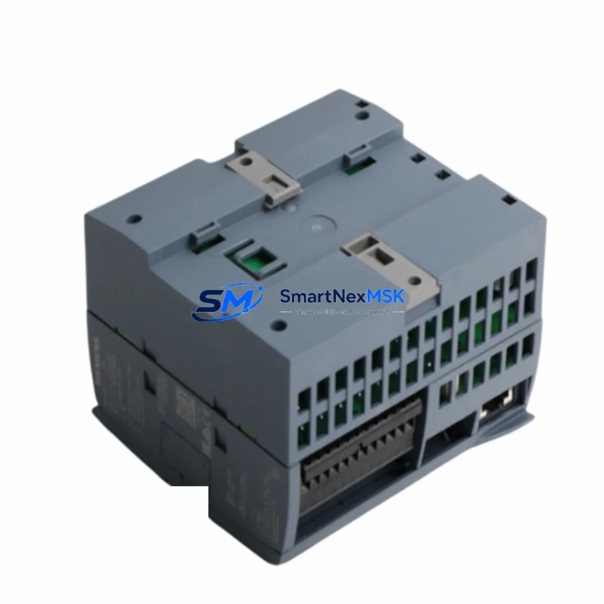
Siemens 6ES7214-1BG40-0XB0 Spare for S7-1200 Automation: Spare Part Replacement & Industrial Downtime Risk Control
The Siemens 6ES7214-1BG40-0XB0 is the CPU 1214C DC/DC/DC module within the SIMATIC S7-1200 compact PLC family — a workhorse controller deployed across discrete manufacturing, conveyor systems, packaging lines, water treatment facilities, and building automation infrastructure worldwide. When this CPU fails or reaches end-of-service life, the entire control loop it governs goes offline. Sourcing a verified, original-spec replacement quickly is not optional — it is the difference between a two-hour recovery and a two-day production loss.
At SMARTNEXMSK, every 6ES7214-1BG40-0XB0 unit is sourced from authorized supply chains, individually inspected, and shipped with full documentation. Our 12-month warranty covers functional performance under normal industrial operating conditions, giving maintenance engineers and procurement teams the confidence to stock this CPU as a critical spare.
Spare Maintenance Table
| Parameter | Specification |
|---|---|
| Part Number / SKU | 6ES7214-1BG40-0XB0 |
| Product Family | SIMATIC S7-1200 |
| Module Type | CPU 1214C DC/DC/DC |
| Power Supply Input | DC 24 V |
| Digital Inputs (Onboard) | 14 × DI (24 V DC) |
| Digital Outputs (Onboard) | 10 × DO (Transistor, 0.5 A) |
| Analog Inputs (Onboard) | 2 × AI (0–10 V) |
| Work Memory | 100 KB |
| Communication Interface | 1 × PROFINET (RJ45) |
| Signal Board Slot | 1 × SB (expandable) |
| Signal Module Expansion | Up to 8 × SM |
| Communication Module Expansion | Up to 3 × CM |
| Operating Temperature | 0 °C to +55 °C |
| Protection Rating | IP20 |
| Mounting | DIN Rail / Panel |
| Origin | Germany |
| Compatibility | SIMATIC S7-1200 Series (V4.x firmware) |
| Warranty | 12 Months |
| Condition | Original Spare — New / Tested |
| Shipping | Global Express, ESD-safe packaging |
Maintenance Planning for Continuous Operation
Replacing the 6ES7214-1BG40-0XB0 is rarely an isolated task. A disciplined maintenance engineer treats a CPU swap as an opportunity to audit the entire control cabinet. Before commissioning the replacement CPU, verify the 24 V DC power supply module — such as the Siemens SITOP PSU100S or equivalent — is delivering stable voltage within tolerance, since an under-voltage condition is a common root cause of CPU brownout failures that are misdiagnosed as CPU hardware faults.
Inspect the signal modules connected to the CPU rail. Digital input modules (e.g., SM 1221 6ES7221-1BF32-0XB0) and digital output modules (e.g., SM 1222 6ES7222-1BF32-0XB0) should be checked for blown fuse indicators, damaged terminal blocks, and loose wiring on the I/O terminal strips. Analog signal modules (e.g., SM 1231 6ES7231-4HD32-0XB0) require verification of signal loop integrity — a shorted 4–20 mA loop can cause erratic CPU behavior that survives a CPU replacement if the root cause is not isolated.
Communication modules installed in the CM slots — such as the CM 1241 RS485 module (6ES7241-1CH32-0XB0) for serial device integration or the CM 1243-5 PROFIBUS DP master — should be inspected for firmware version compatibility with the replacement CPU’s firmware. A firmware mismatch between the CPU and communication modules is a known cause of post-replacement communication faults that delay restart.
If a Signal Board (SB) is installed in the CPU’s onboard SB slot — for example, the SB 1232 analog output board (6ES7232-4HA30-0XB0) — confirm it is seated correctly and that its configuration in the TIA Portal project matches the physical hardware. The SIMATIC Memory Card (6ES7954-8LF03-0AA0) used for program backup and firmware transfer should also be inspected and replaced if it shows read errors during the CPU startup sequence.
For cabinets with HMI integration, verify the KTP700 Basic or KTP900 Basic panel communication settings match the new CPU’s IP address if it has been reassigned. Relay output modules and intermediate relay terminals in the output circuit should be tested for contact wear, particularly in high-cycle applications. Signal isolators and surge protection devices on field wiring inputs are often overlooked during CPU replacements but are critical for long-term CPU protection in electrically noisy environments.
Site Replacement Workflow
Step 1 — Backup & Documentation: Before removing the failed CPU, use the SIMATIC Memory Card to back up the existing program if the CPU is still partially functional. If not, retrieve the project from the TIA Portal engineering station. Document the current IP address, device name, and subnet configuration.
Step 2 — Safe Isolation: De-energize the control cabinet following your site LOTO (Lockout/Tagout) procedure. Confirm 24 V DC supply is isolated before disconnecting the CPU wiring connectors. The 6ES7214-1BG40-0XB0 uses plug-in front connectors — label each connector position before removal to prevent wiring errors during reinstallation.
Step 3 — Physical Replacement: Remove the failed CPU from the DIN rail. Install the replacement 6ES7214-1BG40-0XB0 and reconnect all front connectors in their original positions. Ensure the SIMATIC Memory Card is inserted if program transfer via card is planned.
Step 4 — Firmware & Program Restore: Power up the cabinet and allow the CPU to complete its startup sequence. Download the TIA Portal project to the CPU via PROFINET. Verify firmware version compatibility with all installed signal modules and communication modules. Update firmware if required before going online.
Step 5 — Functional Verification: Perform I/O force tests on all digital and analog channels. Confirm PROFINET communication with all distributed I/O nodes and HMI panels. Verify serial communication on CM modules. Run the machine through a dry cycle before resuming production.
This structured workflow minimizes restart time, reduces the risk of secondary faults, and ensures the replacement CPU is fully validated before production load is applied — a critical discipline for aging S7-1200 installations where surrounding components may also be approaching end-of-life.
Spare Parts Support FAQ
Q1: Is the 6ES7214-1BG40-0XB0 a direct drop-in replacement for older S7-1200 CPU 1214C variants?
The 6ES7214-1BG40-0XB0 (firmware V4.x) is hardware-compatible with the S7-1200 rail and uses the same front connector layout as earlier CPU 1214C variants. However, firmware version differences may require a TIA Portal project update before download. Always verify the TIA Portal version used to create the original project against the replacement CPU’s supported firmware range before commissioning.
Q2: How does SMARTNEXMSK verify the condition of spare CPUs before shipment?
Each unit undergoes a pre-shipment functional check including power-on startup verification, memory integrity test, and PROFINET port communication test. Units are packed in ESD-safe anti-static bags with foam cushioning and shipped in double-wall cartons. A test report is available upon request for critical spare orders.
Q3: What is the recommended inventory strategy for the 6ES7214-1BG40-0XB0 in a multi-line facility?
For facilities operating three or more S7-1200-controlled lines, we recommend maintaining a minimum of one cold-spare CPU per five installed units, with a maximum replenishment lead time target of 48 hours. Given that Siemens has announced the S7-1200 V4 series as a long-term product, stocking one pre-configured spare with a loaded SIMATIC Memory Card significantly reduces mean time to repair (MTTR) during unplanned outages.
Q4: What does the 12-month warranty cover, and how is a warranty claim processed?
The 12-month warranty covers manufacturing defects and functional failures under normal industrial operating conditions (within specified voltage, temperature, and environmental ratings). It does not cover damage from incorrect wiring, overvoltage events, or physical impact. To initiate a warranty claim, contact [email protected] with the order number, failure description, and photos of the unit. Replacement or repair is processed within 5–7 business days of unit receipt.
© 2026 SMARTNEXMSK. All rights reserved.
Original Source: https://smartnexmsk.com
Contact: [email protected] | +86 18259474341



