
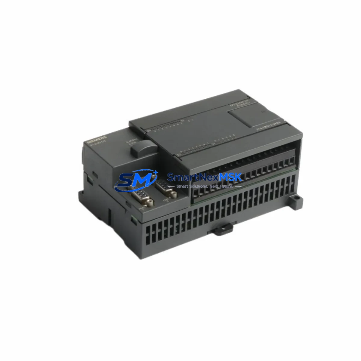
Siemens 6ES7214-2BD23-0XB8 Retrofit-Ready CPU for S7-200 Control Systems
The Siemens 6ES7214-2BD23-0XB8 is a high-performance CPU 224 XP module designed for the S7-200 Micro PLC platform. As legacy S7-200 systems approach end-of-life and original Siemens production has been discontinued, this unit serves as a direct retrofit-ready replacement for aging control cabinets, standalone machine controllers, and distributed automation panels originally built around the S7-200 architecture. Whether you are managing a planned upgrade, responding to an unplanned failure, or executing a phased modernization of your production line, the 6ES7214-2BD23-0XB8 provides a wiring-compatible, program-compatible, and communication-compatible path forward without requiring a full system redesign.
This CPU module features 14 digital inputs and 10 digital outputs onboard, with two analog inputs and one analog output integrated directly on the CPU — a key differentiator of the XP variant compared to the standard CPU 224. It supports 24 VDC supply voltage, making it directly interchangeable with existing 24 V panel wiring in most retrofit scenarios. The module supports PPI, MPI, and Freeport communication protocols, ensuring backward compatibility with existing HMI panels such as the Siemens TD 400C text display or TP 177 touch panels, as well as third-party SCADA systems connected via RS-485 serial links.
Program memory capacity of 12 KB and data memory of 10 KB are sufficient to retain existing STEP 7 Micro/WIN ladder logic programs without modification in the majority of S7-200 retrofit cases. The onboard real-time clock supports time-stamped event logging and scheduled control routines, which is particularly important in food processing, water treatment, and building automation applications where the original S7-200 CPU 224 or CPU 222 was deployed.
Upgrade Compatibility Table
| Parameter | Details |
|---|---|
| Replaces / Compatible With | 6ES7214-2AD23-0XB8 (CPU 224 XP AC/DC/Relay), 6ES7212-1BB23-0XB8 (CPU 222), 6ES7214-1BD23-0XB8 (CPU 224 DC/DC/DC) |
| Supply Voltage | 24 VDC (same as original S7-200 CPU 224 XP DC variant) |
| Digital I/O | 14 DI / 10 DO (transistor output) |
| Analog I/O (onboard) | 2 AI / 1 AO — no additional EM 235 analog expansion required for basic loops |
| Communication Ports | Port 0 & Port 1: RS-485, PPI / MPI / Freeport |
| Expansion Module Support | Up to 7 expansion modules (EM 221, EM 222, EM 223, EM 231, EM 232, EM 235, CP 243-1) |
| Program Memory | 12 KB (retains existing STEP 7 Micro/WIN programs without recompilation in most cases) |
| Installation | DIN rail mount, same footprint as CPU 224 — no panel modification required |
| Programming Software | STEP 7 Micro/WIN V4.0 SP9 or later; compatible with PC/PPI cable 6ES7901-3CB30-0XA0 |
| Retrofit Commissioning | Restore program via memory card or PC/PPI cable; verify I/O address mapping and analog scaling |
| Warranty | 12 months from date of shipment — covers manufacturing defects and functional failure under normal operating conditions |
Retrofit Planning for Existing Automation Systems
A successful retrofit of the 6ES7214-2BD23-0XB8 into an existing S7-200 control system begins with a thorough pre-replacement audit. Before removing the original CPU, engineers should document the current program using STEP 7 Micro/WIN and back up the project to both a PC and a Siemens memory card (6ES7291-8GF23-0XA0) if one is installed. This ensures that the ladder logic, symbol table, data block values, and system block configuration — including PPI baud rate, station address, and analog filter settings — are preserved and can be restored immediately after the new CPU is seated.
Terminal wiring on the S7-200 CPU 224 XP uses a removable screw-terminal connector block, which means the existing field wiring harness can be unplugged from the old unit and transferred directly to the replacement 6ES7214-2BD23-0XB8 without re-terminating individual conductors. This significantly reduces retrofit time and eliminates the risk of miswiring during the changeover. Verify that the 24 VDC supply from the existing power supply module — commonly a Siemens SITOP PSU100S or equivalent industrial DIN-rail PSU — meets the current draw requirements of the new CPU plus all connected expansion modules.
If the existing system includes expansion modules such as the EM 221 digital input module, EM 222 digital output module, EM 223 combined I/O module, or EM 231 analog input module, these can remain in place on the existing DIN rail. The 6ES7214-2BD23-0XB8 uses the same I/O bus connector and expansion cable as the original CPU 224 XP, so no mechanical changes to the expansion rack are required. For systems that include an EM 277 PROFIBUS-DP module for fieldbus connectivity, verify that the PROFIBUS station address and GSD file configuration in the master PLC remain unchanged after the CPU swap.
Communication links to HMI devices must also be validated. If the original system used a Siemens TP 177A or TP 177B touch panel connected via PPI on Port 0, the replacement CPU will communicate using the same protocol and baud rate settings stored in the system block. For systems using a CP 243-1 Ethernet module for remote monitoring or OPC connectivity, the IP address and connection parameters stored in the CP module are independent of the CPU and will not be affected by the CPU swap. Similarly, any Freeport communication routines used for barcode scanner integration, weighing terminal communication, or custom serial protocols will execute correctly on the new CPU provided the program is restored from backup.
After physical installation and program restore, perform a full I/O force test to verify that all digital inputs, digital outputs, and analog channels respond correctly. Pay particular attention to the onboard analog inputs (AIW0, AIW2) and analog output (AQW0), as scaling constants in the program may need to be verified against the actual sensor signal range. If the original system used a CPU 222 or CPU 224 (non-XP) without onboard analog I/O, and an EM 235 analog combination module was used instead, confirm that the I/O address assignments in the program are updated to reflect the new analog channel locations on the XP CPU.
Downtime Control During System Migration
Minimizing production downtime during a CPU replacement is the primary concern for most maintenance engineers working with legacy S7-200 systems. The 6ES7214-2BD23-0XB8 is designed to support a rapid swap procedure that, when properly prepared, can be completed within a planned maintenance window of 30 to 60 minutes for a standard single-CPU installation.
The recommended approach is to prepare the replacement CPU in advance by loading the backed-up program and system block configuration onto the new unit in a workshop environment using a PC/PPI cable (6ES7901-3CB30-0XA0) and STEP 7 Micro/WIN before the scheduled maintenance window. This pre-loading step eliminates the need for programming during the live changeover and reduces the risk of errors under time pressure. If a Siemens memory card (6ES7291-8GF23-0XA0) is used, the program can be transferred to the new CPU automatically on first power-up, further simplifying the on-site procedure.
During the changeover, the existing output states should be noted or photographed so that the system can be returned to its pre-shutdown state after restart. For processes where a controlled shutdown sequence is required — such as conveyor systems, packaging lines, or HVAC control panels — the original program’s stop routine should be executed before power is removed from the CPU. This protects downstream equipment and preserves the integrity of any in-process batches or sequences.
After the new 6ES7214-2BD23-0XB8 is installed and powered, perform a RUN mode test with all field devices in a safe state before resuming normal production. Monitor the CPU’s diagnostic LEDs (SF, RUN, STOP, I/O) during the first power cycle to confirm that no system faults are present. If the SF (System Fault) LED illuminates, connect STEP 7 Micro/WIN and review the system error log to identify the fault source before proceeding. In most cases, SF faults at first startup are caused by mismatched expansion module configurations or incorrect system block settings, both of which can be resolved quickly without additional hardware.
Retrofit Support FAQ
Q1: Is the 6ES7214-2BD23-0XB8 a direct drop-in replacement for the CPU 224 XP DC/DC/DC?
Yes. The 6ES7214-2BD23-0XB8 is the standard catalog designation for the S7-200 CPU 224 XP with 24 VDC supply, transistor (DC) outputs, and 24 VDC sensor supply. It is dimensionally identical to the original CPU 224 XP, uses the same terminal connector block, and supports the same expansion bus. Programs developed for the original CPU 224 XP can be restored directly without modification in the vast majority of applications.
Q2: Can I reuse my existing expansion modules and wiring?
Yes. All S7-200 expansion modules — including EM 221, EM 222, EM 223, EM 231, EM 232, EM 235, EM 277, and CP 243-1 — are compatible with the 6ES7214-2BD23-0XB8. The expansion bus connector and cable are identical to those used on all S7-200 CPU variants. Field wiring connected to the removable terminal blocks on expansion modules does not need to be disturbed during the CPU replacement.
Q3: What programming cable and software are required for commissioning?
The 6ES7214-2BD23-0XB8 is programmed using STEP 7 Micro/WIN V4.0 SP9 (or later) running on a Windows PC. The recommended programming cable is the PC/PPI cable 6ES7901-3CB30-0XA0 (USB to RS-485). Alternatively, a CP 5711 PROFIBUS adapter can be used for MPI-based programming. No additional license is required beyond the standard STEP 7 Micro/WIN installation.
Q4: What does the 12-month warranty cover, and what is the shipping and testing process?
All units are function-tested prior to shipment, including power-on verification, I/O channel testing, and communication port validation. The 12-month warranty covers manufacturing defects and functional failure under normal operating conditions from the date of shipment. Units are shipped with ESD-protective packaging and include a test report on request. In the event of a warranty claim, replacement or repair is arranged with priority handling to minimize your system downtime.
© 2026 SMARTNEXMSK. All rights reserved.
Original Source: https://smartnexmsk.com
Contact: [email protected] | +86 18259474341



