
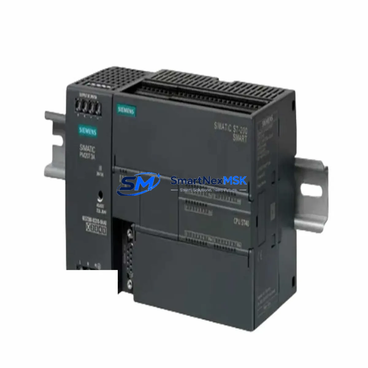
Siemens 6ES7223-1PM22-0XA8: Retrofit-Ready 8DI/8DO Relay Module for S7-200 Control Systems
The Siemens 6ES7223-1PM22-0XA8 is an 8-input / 8-output relay digital expansion module designed for the S7-200 Micro PLC platform. As the S7-200 series has reached end-of-life status, sourcing verified replacement units for legacy production lines, control cabinets, and OEM machinery has become a critical operational challenge. This module provides a direct, drop-in retrofit solution for facilities that need to maintain continuity of existing S7-200-based automation without a full platform migration.
Whether you are replacing a failed unit on a running line, building a spare-parts buffer for a multi-year maintenance contract, or executing a phased upgrade of an aging control system, the 6ES7223-1PM22-0XA8 delivers the relay output capacity, terminal compatibility, and backplane interface required for seamless integration into your existing S7-200 rack architecture.
Upgrade Compatibility Table
| Parameter | Details |
|---|---|
| SKU / Part Number | 6ES7223-1PM22-0XA8 |
| Brand | Siemens |
| Series | S7-200 SIMATIC Micro PLC |
| Compatible Platform | S7-200 Micro PLC Series (CPU 222, CPU 224, CPU 224 XP, CPU 226) |
| Digital Inputs | 8 × 24 VDC |
| Digital Outputs | 8 × Relay (2 A per point, 250 VAC / 30 VDC max) |
| Backplane Interface | S7-200 Expansion Bus (I/O Bus Connector) |
| Installation | DIN Rail or Panel Mount |
| Supply Voltage | 24 VDC (from CPU or external 24 V supply) |
| Communication Compatibility | PPI, MPI (via S7-200 CPU) |
| Replacement Recommendation | Direct replacement for 6ES7223-1PM22-0XA0 and earlier 0XA8 revisions |
| Commissioning Notes | Verify module address offset in STEP 7 Micro/WIN; confirm I/O byte mapping before program download |
| Origin | China (CN) |
| Warranty | 12 Months — covers manufacturing defects and functional failure under normal operating conditions |
Retrofit Planning for Existing Automation Systems
Integrating the 6ES7223-1PM22-0XA8 into a legacy control system requires a structured pre-installation review. Begin by auditing the existing S7-200 CPU — typically a CPU 224 XP, CPU 226, or CPU 222 — to confirm the total expansion module count does not exceed the CPU’s supported limit (up to 7 expansion modules for CPU 226). The expansion bus ribbon cable or direct bus connector must be inspected for wear, as aged connectors are a common source of intermittent I/O faults after module replacement.
Power budget verification is essential before installation. The 6ES7223-1PM22-0XA8 draws current from the 24 VDC bus supplied by the CPU or an external PS 307 24 VDC power supply module. If the existing power supply is already near capacity — particularly in cabinets that also power EM 231 analog input modules, EM 232 analog output modules, or communication processors — an additional 24 V rail may be required to avoid voltage sag under load.
Terminal wiring must be mapped against the original I/O schedule. The relay output terminals on the 6ES7223-1PM22-0XA8 use a removable screw-terminal block, which simplifies field rewiring during a hot-swap replacement. Confirm that the load wiring — particularly for motor contactors, solenoid valves, and pilot lights — matches the relay contact rating. For inductive loads, verify that suppression diodes or RC snubbers are in place to protect relay contacts.
Module address assignment is handled automatically by the S7-200 CPU based on physical slot position in the expansion chain. After installing the replacement module, open STEP 7 Micro/WIN and verify that the system block reflects the correct I/O byte addresses. If the module order has changed — for example, if a failed EM 223 digital combination module was removed and the 6ES7223-1PM22-0XA8 inserted in a different position — the I/O byte offsets will shift, requiring a program review and possible address remapping before the next download.
For sites running TD 200 text display panels or TP 177 HMI panels connected via PPI protocol, confirm that the HMI screen tags referencing the replaced module’s I/O addresses remain valid after the address audit. A mismatch between HMI tag addresses and the updated system block is a common commissioning error that can cause false alarms or loss of operator visibility on the first restart.
If the retrofit is part of a broader migration toward the S7-1200 platform, the 6ES7223-1PM22-0XA8 can serve as a bridge module during the transition period — maintaining relay output capacity on the legacy rack while new SM 1222 relay output signal modules are staged for the incoming S7-1200 CPU. This phased approach avoids a full cutover and allows program logic to be validated in parallel.
Downtime Control During System Migration
Minimizing unplanned downtime during an S7-200 module replacement requires preparation before the maintenance window opens. The first step is to upload and archive the current CPU program using STEP 7 Micro/WIN, saving both the program block (OB1, SBRs, INTs) and the system block (hardware configuration, PPI address, retentive memory settings) to a secure backup location. Do not rely solely on the program stored in the CPU — a failed CPU or corrupted memory card can result in permanent program loss if no offline backup exists.
Before powering down the cabinet, document the current I/O status using the Micro/WIN status chart or a connected PC/PPI+ programming cable (such as the 6ES7901-3CB30-0XA0 USB-to-PPI adapter). Capture the live state of all relay outputs and digital inputs so that the post-replacement functional test has a clear baseline for comparison.
During the physical swap, label all terminal wiring before disconnection. The removable terminal block on the 6ES7223-1PM22-0XA8 allows the wiring harness to be transferred as a unit if the terminal block from the failed module is reused — reducing rewiring time and the risk of miswiring. After seating the new module on the expansion bus, restore power and allow the CPU to complete its startup diagnostic cycle before attempting a program download.
Post-replacement commissioning should include a forced I/O test of all 8 relay outputs and 8 digital inputs using the STEP 7 Micro/WIN force table, confirming that each point responds correctly before returning the system to automatic mode. For critical processes — such as conveyor interlocks, press safety circuits, or HVAC control loops — a supervised manual test cycle is recommended before releasing the line to production.
Retrofit Support FAQ
Q1: Is the 6ES7223-1PM22-0XA8 a direct replacement for the 6ES7223-1PM22-0XA0?
Yes. The 0XA8 revision is the current production variant and is functionally and electrically compatible with earlier 0XA0 revisions. Terminal pinout, backplane connector, and I/O specifications are identical. No program changes are required when substituting one revision for the other.
Q2: What commissioning steps are required after installing the replacement module?
After physical installation, power up the S7-200 CPU and open STEP 7 Micro/WIN. Navigate to the system block and confirm that the module is recognized in the correct expansion slot position. Verify I/O byte addresses match the existing program. Perform a forced I/O test on all 16 points (8 DI + 8 DO) before returning to automatic operation. If the CPU shows a configuration error LED, re-download the system block with the updated hardware configuration.
Q3: Can this module be used with an S7-1200 or S7-300 CPU?
No. The 6ES7223-1PM22-0XA8 uses the S7-200 proprietary expansion bus and is not compatible with S7-1200 or S7-300 backplane architectures. For S7-1200 applications, the equivalent relay output module is the SM 1222 (e.g., 6ES7222-1HF32-0XB0 for 8-point relay output). For S7-300 platforms, the SM 322 relay output module family applies.
Q4: What does the 12-month warranty cover?
All units are covered by a 12-month warranty from the date of shipment. The warranty covers manufacturing defects, functional failure under normal operating conditions, and DOA (dead-on-arrival) units. Each module undergoes pre-shipment functional testing including I/O point verification and bus communication check. Warranty claims are processed via our sales team with a standard RMA procedure. Units damaged by incorrect wiring, overvoltage, or physical impact are not covered under warranty terms.
© 2026 SMARTNEXMSK. All rights reserved.
Original Source: https://smartnexmsk.com
Contact: [email protected] | +86 18259474341



