
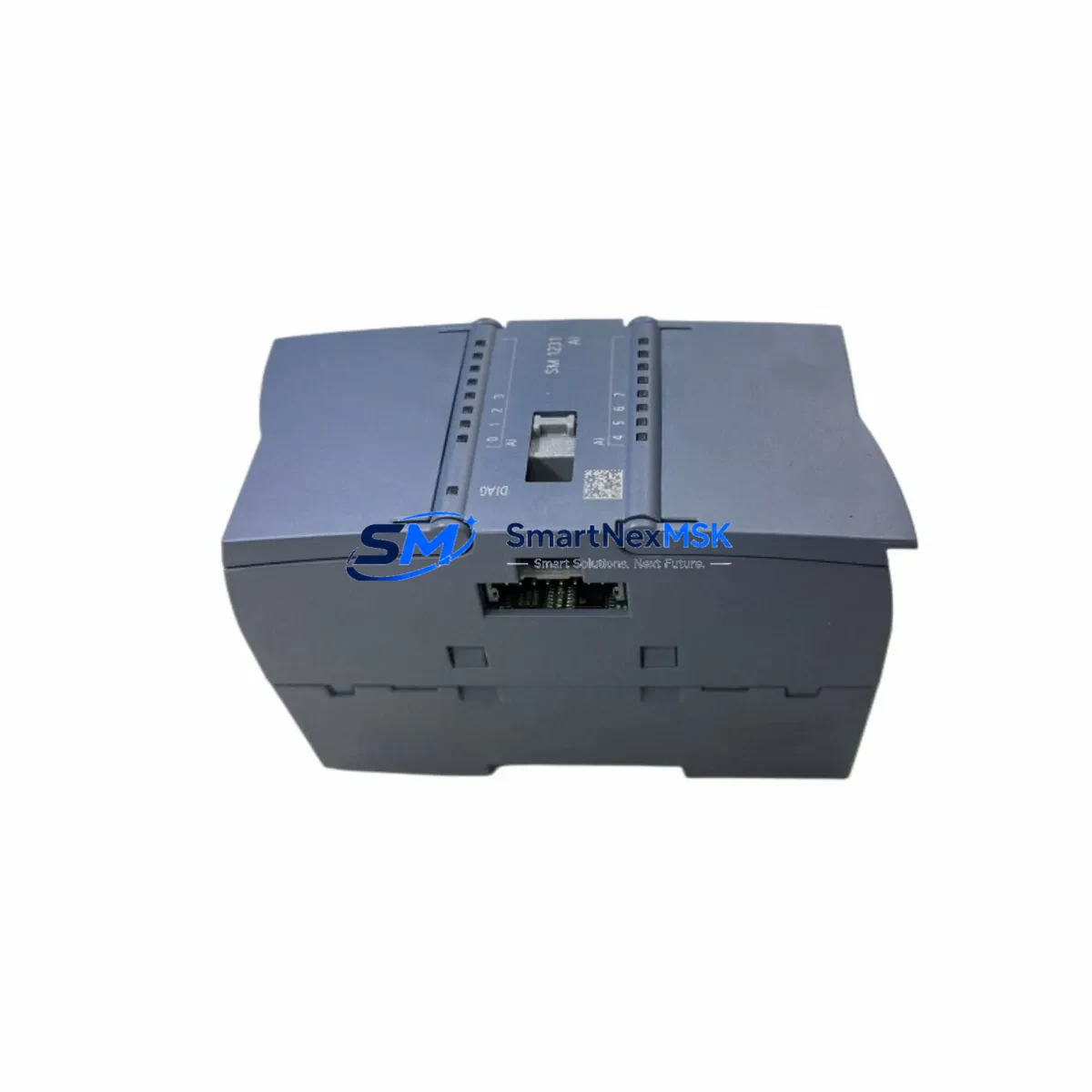
Siemens 6ES7231-4HF32-0XB0 Maintenance-Ready Spare S7-1200 SM 1231: Spare Parts Replacement & Industrial Downtime Risk Control
The Siemens 6ES7231-4HF32-0XB0 is an SM 1231 series 8-channel analog input signal module designed for the S7-1200 programmable logic controller platform. In industrial maintenance environments — from continuous process lines to discrete manufacturing cells — this module occupies a critical position in the I/O architecture. When it fails or degrades, the entire control loop dependent on its analog signal acquisition is compromised, triggering unplanned downtime that can cascade across upstream and downstream processes.
Stocking the 6ES7231-4HF32-0XB0 as a verified maintenance-ready spare is a foundational practice for any facility running S7-1200-based automation. Whether your maintenance team is executing a scheduled annual shutdown, responding to a fault alarm at 2 AM, or conducting a routine control cabinet inspection, having this module on the shelf — tested, original, and ready to install — is the difference between a 20-minute swap and a multi-day production halt waiting for emergency procurement.
This listing supplies the original Siemens 6ES7231-4HF32-0XB0 SM 1231 module, sourced from authorized channels, individually inspected, and shipped with a 12-month warranty. Every unit undergoes pre-shipment functional verification to confirm signal integrity, channel isolation, and firmware compatibility with current S7-1200 CPU generations including the CPU 1211C, CPU 1212C, CPU 1214C, CPU 1215C, and CPU 1217C.
Spare Maintenance Table
| Parameter | Specification |
|---|---|
| Part Number / SKU | 6ES7231-4HF32-0XB0 |
| Module Series | SM 1231 — Signal Module Analog Input |
| Compatible PLC Platform | Siemens S7-1200 Series |
| Number of Analog Input Channels | 8 Channels |
| Input Signal Types | Voltage (±10V, ±5V, ±2.5V, 0–5V, 0–10V) / Current (0–20mA, 4–20mA) |
| Resolution | 13-bit + sign (voltage); 13-bit (current) |
| Conversion Time per Channel | 625 µs (typical) |
| Supply Voltage | 24 VDC (via S7-1200 backplane bus) |
| Isolation | Optically isolated between field side and logic side |
| Operating Temperature | 0°C to +55°C (horizontal mounting); 0°C to +45°C (vertical) |
| Storage Temperature | -40°C to +70°C |
| Degree of Protection | IP20 |
| Mounting | DIN rail, right-side expansion slot of S7-1200 CPU |
| Dimensions (W×H×D) | 45 mm × 100 mm × 75 mm (approx.) |
| Weight | Approx. 200 g |
| Country of Origin | Germany |
| Firmware Compatibility | Compatible with TIA Portal V13 SP1 and above |
| Replacement Scope | Direct drop-in replacement for existing 6ES7231-4HF32-0XB0 installations |
| Pre-Shipment Testing | Functional verification on all 8 channels prior to dispatch |
| Warranty | 12 Months from date of shipment |
Maintenance Planning for Continuous Operation
When a maintenance or procurement engineer identifies the 6ES7231-4HF32-0XB0 as a replacement requirement, the replacement event should be treated as a trigger for a broader control cabinet inspection. Analog input modules do not fail in isolation — their degradation is often symptomatic of upstream power quality issues, wiring fatigue, or environmental stress that affects adjacent components simultaneously.
Begin by verifying the 24 VDC supply rail feeding the S7-1200 expansion bus. A failing or undersized Siemens SITOP PSU100S 24V power supply module can introduce ripple that corrupts analog readings before the module itself fails. Inspect the 6ES7290-1AA30-0XA0 bus connector linking the SM 1231 to the CPU — oxidized or loose bus connectors are a common root cause of intermittent channel faults that are misdiagnosed as module failure.
Check the S7-1200 CPU’s digital output module (such as the SM 1222 or SM 1223 combined I/O module) for signs of relay contact wear if the system uses relay-switched analog signal sources. Relay contact degradation can introduce noise into the 4–20mA or 0–10V signal loops monitored by the 6ES7231-4HF32-0XB0. Similarly, inspect the terminal blocks and signal wiring on the field side — loose Weidmüller or Phoenix Contact terminal connections are a frequent source of signal drift that appears as module error.
For systems using the S7-1200 with a CM 1241 RS485/RS232 communication module or a CB 1241 RS485 communication board, verify that communication integrity is maintained after the analog module swap, as TIA Portal may require a hardware configuration download to re-recognize the new module. If the installation includes a Siemens KTP700 or KTP900 Basic HMI panel, confirm that analog tag bindings remain intact post-replacement and that no alarm suppression was active during the fault period.
In facilities with signal isolation requirements — particularly where the analog inputs monitor sensors in high-voltage or electrically noisy environments — consider inspecting the signal isolators or galvanic separators (such as Phoenix Contact MINI MCR or Pepperl+Fuchs KFD series) installed between field transmitters and the SM 1231 input terminals. These isolators protect the module from transient damage and their condition directly affects measurement accuracy. Additionally, review the fuse protection on the 24V supply circuit and the field sensor supply lines — blown or degraded fuses are often overlooked during module replacement and can cause the new module to appear faulty immediately after installation.
For aging S7-1200 systems approaching end-of-service-life, a proactive spare parts kit should include the 6ES7231-4HF32-0XB0 alongside the SM 1232 analog output module (6ES7232-4HB32-0XB0) if the system uses both input and output analog loops, as well as a spare S7-1200 CPU module appropriate to the installed variant. This approach supports a complete system restoration capability without dependency on spot-market procurement during a production emergency.
Site Replacement Workflow
Step 1 — Pre-Replacement Preparation: Before powering down, use TIA Portal online diagnostics to capture the current module configuration, channel assignments, and any active alarms. Export the hardware configuration as a reference. Confirm the replacement 6ES7231-4HF32-0XB0 carries the same firmware baseline or a compatible newer version.
Step 2 — Safe Isolation: De-energize the S7-1200 system following your site LOTO (Lockout/Tagout) procedure. Disconnect field wiring from the SM 1231 terminal block, labeling each wire by channel number. Remove the bus connector carefully to avoid bending the bus interface pins on the CPU or adjacent modules.
Step 3 — Module Swap: Slide the new 6ES7231-4HF32-0XB0 onto the DIN rail and engage the bus connector. Reconnect field wiring in channel order. The SM 1231 is a direct mechanical and electrical replacement — no hardware jumper changes are required for standard voltage/current input configurations.
Step 4 — Configuration Restore: Power up the system and use TIA Portal to perform a hardware detection or download the saved configuration to the CPU. Verify that all 8 analog channels report expected engineering unit values within calibration tolerance. Compare live readings against known-good reference values from your process historian or SCADA system.
Step 5 — Functional Validation: Run the system through a complete I/O check cycle. Confirm that analog signals are within ±0.5% of expected values. Document the replacement in your CMMS (Computerized Maintenance Management System) and update the spare parts inventory record. Return the failed module for failure analysis if root cause investigation is required.
This workflow minimizes mean time to repair (MTTR) and ensures the replacement does not introduce new faults. For legacy S7-1200 installations where the original TIA Portal project file is unavailable, our technical support team can assist with configuration recovery guidance.
Spare Parts Support FAQ
Q1: Is the 6ES7231-4HF32-0XB0 still available as a new original part, or is it end-of-life?
The 6ES7231-4HF32-0XB0 remains available as a current production part within the Siemens S7-1200 SM 1231 family. We maintain stock of original, new-condition units to support both immediate replacement needs and long-term spare parts planning. For facilities managing aging S7-1200 installations, we recommend securing a minimum of one spare unit per installed system to eliminate procurement lead-time risk.
Q2: How do I verify compatibility before installation?
The 6ES7231-4HF32-0XB0 is compatible with all S7-1200 CPU variants (CPU 1211C through CPU 1217C) and requires TIA Portal V13 SP1 or later for configuration. Compatibility is confirmed by matching the module order number exactly — the suffix 0XB0 denotes the current hardware revision. If your system runs an older TIA Portal version, contact us before ordering to confirm firmware alignment.
Q3: What does the 12-month warranty cover, and what is the claims process?
The 12-month warranty covers manufacturing defects, functional failures under normal operating conditions, and DOA (Dead on Arrival) units. It does not cover damage resulting from incorrect installation, overvoltage events, or environmental conditions outside the specified operating range. To initiate a warranty claim, contact [email protected] with your order number, a description of the fault, and any available diagnostic data from TIA Portal. Replacement units are dispatched within 3 business days of claim approval.
Q4: Can you supply multiple units for a plant-wide spare parts standardization program?
Yes. We support bulk procurement for maintenance departments standardizing spare parts across multiple S7-1200 installations. Volume pricing is available for orders of 3 units or more. Each unit in a bulk order undergoes the same individual pre-shipment functional test as single-unit orders. Long-term supply agreements with scheduled delivery are available for facilities with annual maintenance budgets — contact us to discuss your requirements.
© 2026 SMARTNEXMSK. All rights reserved.
Original Source: https://smartnexmsk.com
Contact: [email protected] | +86 18259474341



