
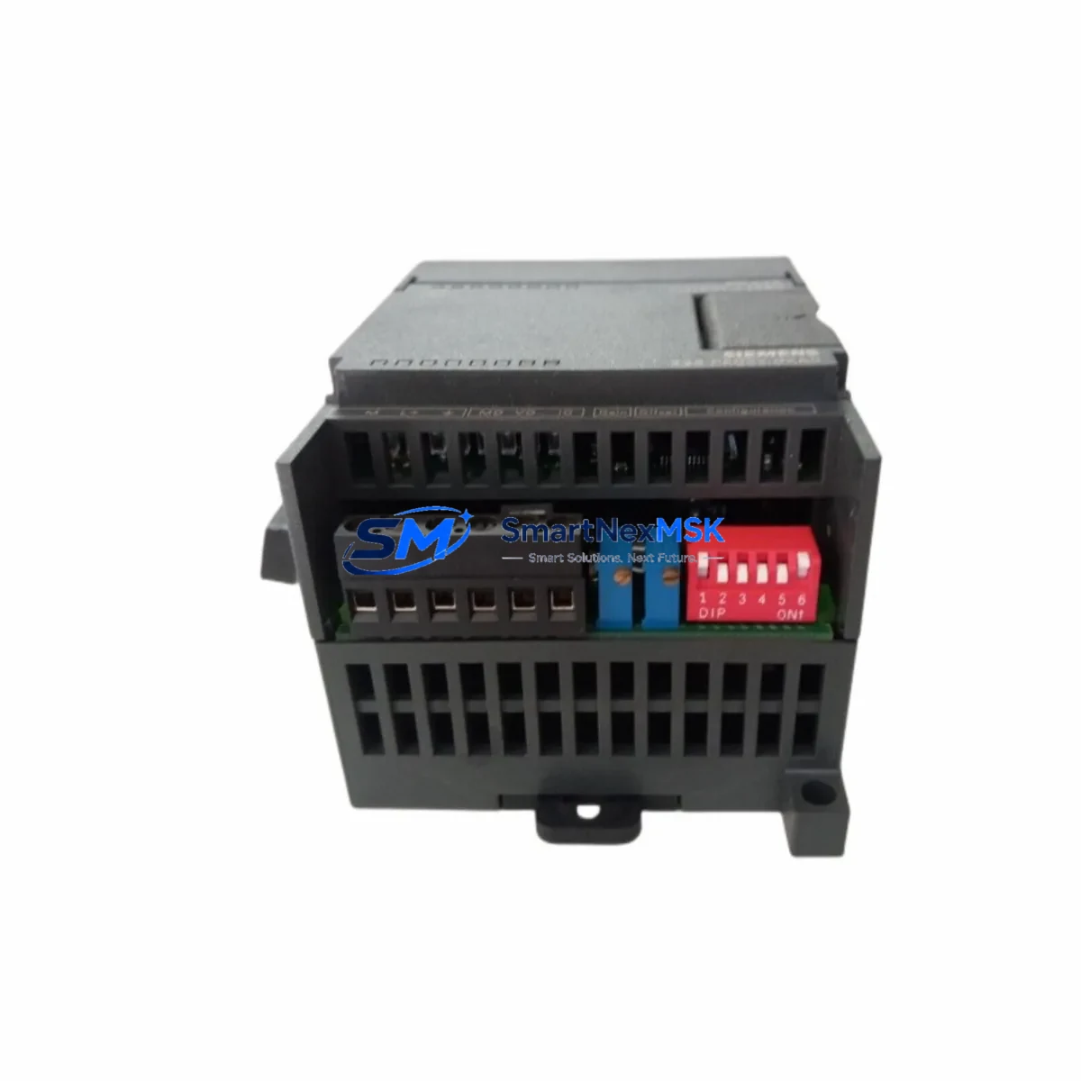
Siemens 6ES7235-0KD22-0XA0: Retrofit-Ready Analog I/O for S7-200 Control Systems
The Siemens 6ES7235-0KD22-0XA0 is the EM 235 analog expansion module for the SIMATIC S7-200 series, providing 4 analog inputs and 1 analog output with 12-bit resolution. As the S7-200 platform reaches end-of-life, this module has become a critical retrofit component for engineers tasked with sustaining legacy production lines, upgrading aging control cabinets, and migrating I/O infrastructure without full system replacement. Whether you are sourcing a direct drop-in replacement for a failed unit or planning a phased modernization of your automation architecture, the 6ES7235-0KD22-0XA0 delivers the signal compatibility and form factor your existing installation demands.
This module mounts directly onto the S7-200 CPU expansion bus — compatible with CPU 221, CPU 222, CPU 224, CPU 224XP, and CPU 226 — and communicates via the proprietary S7-200 I/O bus without requiring additional configuration beyond address assignment in STEP 7 Micro/WIN. The analog inputs accept voltage signals in the ±10 V, 0–10 V, 0–5 V, and ±5 V ranges, as well as current signals in the 0–20 mA and 4–20 mA ranges, making it directly interchangeable with most field transmitters, pressure sensors, temperature transducers, and flow meters already wired into your control cabinet.
Upgrade Compatibility Table
| Parameter | 6ES7235-0KD22-0XA0 (EM 235) | Notes / Retrofit Guidance |
|---|---|---|
| Analog Inputs | 4 × AI (12-bit) | Supports voltage and current ranges; verify field wiring polarity before swap |
| Analog Output | 1 × AO (12-bit) | Check actuator input impedance; output range configurable via DIP switch |
| Supply Voltage | 24 V DC (from CPU bus) | Confirm CPU power budget; add 6ES7902-3AB00-0AA0 expansion cable if needed |
| Bus Interface | S7-200 I/O expansion bus | Direct plug-in; no additional gateway required for S7-200 CPUs |
| Module Address | Auto-assigned by slot position | Verify AIW/AQW addresses in existing STEP 7 Micro/WIN program before replacement |
| Communication Protocol | S7-200 proprietary bus | Not directly compatible with S7-1200/S7-1500 without migration gateway |
| Replacement Compatibility | Direct replacement for 6ES7235-0KD21-0XA0 (older revision) | Firmware revision difference; program logic unchanged |
| Installation | DIN rail, right-side expansion | Maintain minimum 35 mm DIN rail clearance; check cabinet thermal load |
| Commissioning | DIP switch range selection + STEP 7 Micro/WIN calibration | Run analog calibration routine after installation; document offset values |
| Warranty | 12-Month Warranty — covers manufacturing defects; includes pre-shipment functional test | |
Retrofit Planning for Existing Automation Systems
A successful retrofit begins well before the module arrives on site. When replacing the 6ES7235-0KD22-0XA0 in an active production environment, the first step is to document all existing AIW and AQW address assignments in your STEP 7 Micro/WIN project. The S7-200 CPU — whether a CPU 224 or CPU 226 — assigns analog addresses sequentially based on module slot order, so any change in the physical expansion chain will shift addresses for all downstream modules. If your cabinet also includes a 6ES7231-0HC22-0XA0 (EM 231, 4AI) or a 6ES7232-0HB22-0XA0 (EM 232, 2AO), confirm that their addresses remain consistent after the swap.
Power budget verification is equally critical. The S7-200 CPU supplies 24 V DC to the expansion bus, and each EM module draws current from this rail. The EM 235 draws approximately 60 mA from the 5 V logic bus and 60 mA from the 24 V sensor supply. If your cabinet is running a CPU 224 with multiple expansion modules — such as a 6ES7221-1BH22-0XA0 (EM 221, 8DI) and a 6ES7222-1BH22-0XA0 (EM 222, 8DO) — recalculate the total bus current draw to ensure the CPU power supply is not overloaded. In high-density configurations, a dedicated 6EP1331-1SH03 SITOP power supply module may be required to supplement the cabinet power rail.
Terminal wiring must be verified against the original installation drawings. The EM 235 uses a removable screw-terminal connector; confirm that field cable cross-sections (typically 0.5–1.5 mm²) are correctly torqued and that shielded cables are grounded at a single point to prevent ground loops on analog signal lines. For 4–20 mA transmitters, verify loop power sourcing — the EM 235 does not provide loop power, so externally powered transmitters must be confirmed before reconnection.
If your modernization roadmap includes eventual migration from S7-200 to S7-1200, consider installing a CP 243-1 Ethernet communication module alongside the EM 235 to enable remote monitoring during the transition period. This allows the legacy S7-200 system to coexist with a new S7-1200 CPU 1214C on the same network while you validate the migrated program logic in parallel. The 6ES7235-0KD22-0XA0 will continue to serve the legacy line while the new platform is commissioned, minimizing the risk of a hard cutover.
For HMI continuity, if your site uses a SIMATIC OP 73 or TP 177B panel connected to the S7-200 via PPI protocol, verify that the HMI screen tags referencing analog values (AIW0, AIW2, AQW0) are correctly mapped. A module swap that inadvertently shifts the address map will cause incorrect readings on the operator panel without triggering a CPU fault, making this one of the most common post-replacement issues in S7-200 retrofit projects.
Downtime Control During System Migration
Minimizing unplanned downtime during an EM 235 replacement requires a structured pre-outage checklist. Before powering down the cabinet, upload the current CPU program to a PC running STEP 7 Micro/WIN and save a timestamped backup — including the data block and system block — to a secure location. Note the current analog calibration values stored in the module, as these will need to be re-entered or re-calibrated after the new module is installed.
During the physical swap, label all terminal connections before removal. The EM 235’s removable terminal block simplifies this process, but field cables should still be tagged individually to prevent miswiring on reconnection. After installing the replacement 6ES7235-0KD22-0XA0, power up the CPU and verify that the module status LED (green) illuminates without fault. If the CPU displays an I/O error, check the expansion bus connector seating and confirm that the module order in the physical chain matches the configuration in the STEP 7 Micro/WIN system block.
Run the analog calibration routine from STEP 7 Micro/WIN before returning the system to automatic mode. Apply a known reference signal (e.g., a calibrated 4–20 mA source) to each input channel and verify that the AIW values in the CPU data monitor match expected engineering unit conversions. For the analog output, command a known AQW value and measure the output voltage or current at the terminal with a calibrated meter. Document all calibration results and retain them with the maintenance record for the cabinet. This process typically takes 30–60 minutes per module and is the single most effective step for ensuring control continuity after replacement.
Retrofit Support FAQ
Q1: Is the 6ES7235-0KD22-0XA0 a direct drop-in replacement for the older 6ES7235-0KD21-0XA0?
Yes. The -0KD22- revision is backward compatible with the -0KD21- revision in terms of terminal pinout, bus interface, and address assignment. No program changes are required. The only difference is an internal firmware revision that improves analog conversion stability. Both revisions are interchangeable in the field.
Q2: Can this module be used with an S7-1200 or S7-1500 CPU?
No. The EM 235 uses the proprietary S7-200 expansion bus and is not electrically or logically compatible with S7-1200 or S7-1500 signal modules. For S7-1200 systems, the equivalent analog I/O module is the SM 1234 (6ES7234-4HE32-0XB0), which provides 4AI/2AO with PROFINET integration. If you are migrating from S7-200 to S7-1200, the 6ES7235-0KD22-0XA0 should be used to sustain the legacy system during the transition period only.
Q3: What pre-shipment testing is performed on this module?
Each 6ES7235-0KD22-0XA0 unit undergoes a functional test prior to shipment, including power-on verification, bus communication check, and analog I/O signal validation across all channels. Units are shipped with a test report and are covered by a 12-month warranty against manufacturing defects from the date of delivery. Warranty claims are processed within 5 business days of receipt of the returned unit.
Q4: What information should I provide when ordering to ensure compatibility?
Please confirm your CPU model (e.g., CPU 224, CPU 226), the number and type of existing expansion modules in the chain, and the analog signal ranges currently in use (voltage or current, and specific range). If you are replacing a failed module, provide the existing module’s revision label if visible. This allows our technical team to confirm compatibility and advise on any calibration or address considerations specific to your configuration before shipment.
© 2026 SMARTNEXMSK. All rights reserved.
Original Source: https://smartnexmsk.com
Contact: [email protected] | +86 18259474341



