
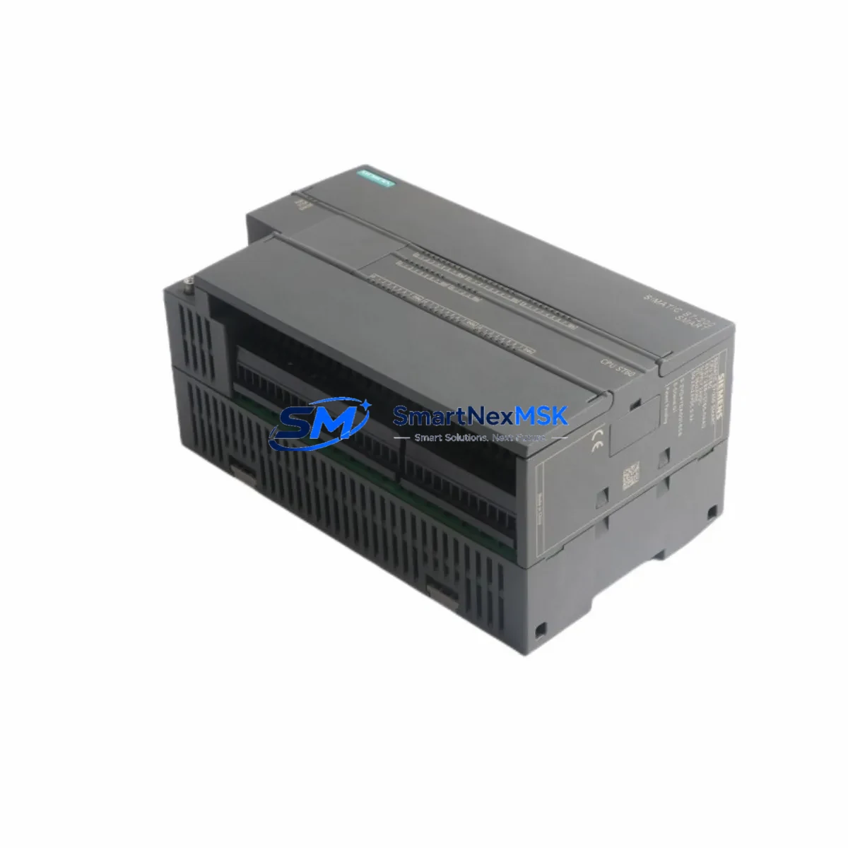
Siemens 6ES7288-1ST60-0AA0 Retrofit-Ready CPU for S7-200 SMART Control Systems
The Siemens 6ES7288-1ST60-0AA0 is a high-performance CPU module from the S7-200 SMART series, purpose-built for industrial automation environments where legacy system continuity, smooth migration, and minimal downtime are critical operational priorities. With 60 onboard I/O points, integrated Ethernet communication, and full compatibility with the STEP 7-Micro/WIN SMART programming environment, this CPU module serves as a direct retrofit solution for aging S7-200 Classic installations and a reliable upgrade path for facilities modernizing their control infrastructure without full panel replacement.
Whether you are replacing a discontinued S7-200 CPU 224XP, decommissioning an obsolete CPU 226, or expanding an existing S7-200 SMART rack with additional processing capacity, the 6ES7288-1ST60-0AA0 delivers the I/O density, communication flexibility, and program memory required to sustain production continuity across diverse industrial sectors including packaging, material handling, water treatment, and discrete manufacturing.
Upgrade Compatibility Table
| Parameter | Details |
|---|---|
| SKU / Part Number | 6ES7288-1ST60-0AA0 |
| Series | Siemens S7-200 SMART |
| Onboard I/O | 36 DI / 24 DO (60 total) |
| Communication Ports | 1× Ethernet (RJ45), 1× RS485 (Port 0) |
| Supported Protocols | Modbus RTU, Modbus TCP, USS, S7 Communication, PROFIBUS (via EM DP01) |
| Programming Software | STEP 7-Micro/WIN SMART V2.x and above |
| Power Supply Compatibility | 24 VDC sensor supply; requires PM207 or equivalent 24 VDC power module |
| Backplane / Rack Interface | Direct left-side expansion bus; compatible with SMART expansion modules |
| Replaces / Upgrades From | S7-200 CPU 224XP, CPU 226, CPU 222, CPU 224 |
| Installation Format | DIN rail mount, standard 35 mm |
| Warranty | 12 Months — covers manufacturing defects, functional failure under normal use |
| Retrofit Recommendation | Verify terminal block pitch (3.81 mm vs 5.08 mm on legacy units) before rewiring |
| Commissioning Note | Re-download program via Ethernet after hardware swap; verify I/O addressing in symbol table |
Retrofit Planning for Existing Automation Systems
A successful retrofit using the 6ES7288-1ST60-0AA0 begins well before the physical hardware swap. Engineers must first audit the existing control cabinet to confirm that the 24 VDC power supply — typically a Siemens PM207 or equivalent third-party DIN rail PSU — can sustain the combined current draw of the new CPU and all attached expansion modules. The S7-200 SMART expansion bus supports up to six expansion modules, including digital I/O modules such as the EM DE08 and EM DT08, analog modules like the EM AE04 and EM AQ02, and specialty modules including the EM DP01 PROFIBUS-DP slave adapter for facilities that must maintain legacy PROFIBUS network segments during a phased migration.
Terminal block compatibility is a frequent source of commissioning delays. The 6ES7288-1ST60-0AA0 uses a 3.81 mm pitch removable terminal block, which differs from the 5.08 mm pitch found on older S7-200 Classic CPUs. Field wiring must be re-terminated or adapted accordingly. Where existing cable lengths are marginal, this is the appropriate stage to extend conductors and re-label all field terminals per the updated I/O map.
Module addressing must be re-verified after installation. The STEP 7-Micro/WIN SMART software automatically assigns I/O addresses based on module slot position, but any deviation from the original S7-200 Classic slot arrangement will require corresponding updates to the PLC program’s symbol table and network logic. Engineers should export the original program from the legacy CPU using a PC/PPI cable or USB-PPI adapter before decommissioning the old hardware, then import and recompile the project in STEP 7-Micro/WIN SMART, resolving any deprecated instruction blocks or unsupported special memory (SM) bit references.
For sites running SIMATIC WinCC flexible or older TP177 and OP77 HMI panels connected via MPI or RS485, the communication link must be reconfigured. The 6ES7288-1ST60-0AA0 supports Modbus RTU on Port 0 (RS485) and Modbus TCP over Ethernet, enabling connection to modern SIMATIC HMI Basic panels such as the KTP700 Basic or KTP400 Basic without requiring a protocol gateway. Where legacy HMI screens reference specific data block addresses or variable tags, the tag table must be updated to reflect the new CPU’s memory organization before going live.
Signal isolation and grounding should be reviewed during the retrofit window. Inductive loads connected to relay output modules — particularly those driving contactors, solenoid valves, or motor starters — should be equipped with suppression diodes or RC snubbers to protect the new CPU’s output circuitry. This is especially important when the EM DR08 relay expansion module is used alongside the 6ES7288-1ST60-0AA0 in high-cycle applications.
Downtime Control During System Migration
Minimizing production downtime during a CPU retrofit requires a structured pre-commissioning strategy. The recommended approach is to prepare and bench-test the replacement 6ES7288-1ST60-0AA0 — complete with all expansion modules, pre-loaded program, and verified I/O configuration — before the scheduled maintenance window. Using a laptop with STEP 7-Micro/WIN SMART connected via Ethernet, engineers can simulate I/O states and validate program logic against the original functional specification without interrupting live production.
During the cutover window, the sequence should follow: power down the control cabinet, document all field wiring terminal assignments with photographs, remove the legacy CPU and expansion modules, install the 6ES7288-1ST60-0AA0 and reconnect field wiring per the updated terminal map, restore 24 VDC power, and perform a forced I/O test on all digital and analog channels before enabling automatic mode. The entire swap — for a well-prepared team — can typically be completed within a two- to four-hour planned maintenance window, preserving the original ladder logic structure and retaining all PID loop parameters, data logging configurations, and communication settings.
Where continuous process control is required and a hard cutover is not feasible, a parallel-run strategy using a temporary EM AE04 analog input module to mirror critical process variables can provide an additional safety layer during the transition period. Once the new CPU has been validated in shadow mode, the final switchover can be executed with confidence that program logic, HMI displays, and field instrument responses are all operating within specification.
Retrofit Support FAQ
Q: Is the 6ES7288-1ST60-0AA0 a direct drop-in replacement for the S7-200 CPU 226?
A: Functionally yes — the 6ES7288-1ST60-0AA0 provides equivalent or greater I/O capacity and supports the same core instruction set. However, the terminal block pitch differs (3.81 mm vs 5.08 mm), so field wiring re-termination is required. The program must also be recompiled in STEP 7-Micro/WIN SMART after migrating from the legacy STEP 7-Micro/WIN Classic environment.
Q: Will my existing PROFIBUS network remain operational after the retrofit?
A: The 6ES7288-1ST60-0AA0 does not include a native PROFIBUS port, but full PROFIBUS-DP slave functionality is available by adding the EM DP01 expansion module to the left expansion bus. This allows the new CPU to participate in an existing PROFIBUS network as a slave device without replacing the PROFIBUS master or reconfiguring the network topology.
Q: What commissioning tests should be performed before returning the system to production?
A: Prior to enabling automatic mode, perform a forced I/O scan on all digital inputs and outputs, verify analog channel scaling against known reference signals, confirm Modbus or Ethernet communication link status with connected HMI and SCADA systems, and execute a timed cycle test to validate PLC scan time against the original baseline. All units supplied by SMARTNEXMSK are pre-tested for functional integrity before shipment.
Q: What does the 12-month warranty cover?
A: The 12-month warranty covers manufacturing defects and functional failure under normal operating conditions, including CPU processing faults, communication port failures, and I/O channel malfunctions. It does not cover damage resulting from incorrect wiring, overvoltage events, or unauthorized modification. Warranty claims are processed directly through SMARTNEXMSK with a target response time of one business day.
© 2026 SMARTNEXMSK. All rights reserved.
Original Source: https://smartnexmsk.com
Contact: [email protected] | +86 18259474341



