
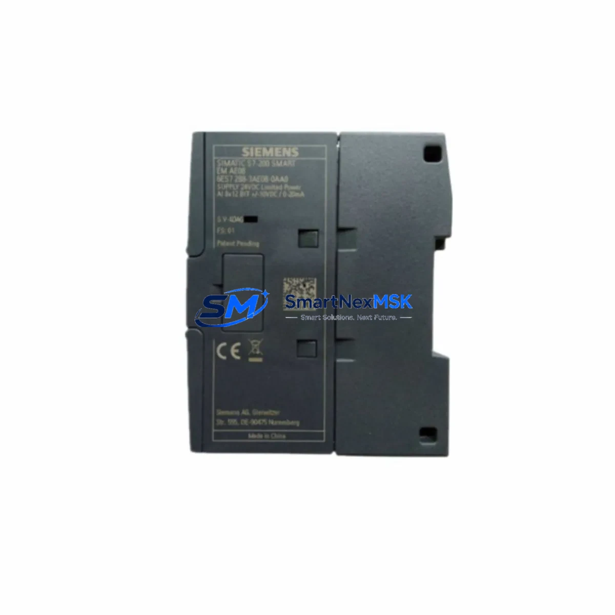
Siemens 6ES7288-3AE08-0AA0 Maintenance-Ready Spare S7-200 SMART
The Siemens 6ES7288-3AE08-0AA0 — designated EM AE08 in the S7-200 SMART expansion module lineup — is an 8-channel analog input / 4-channel analog output module engineered for precision signal acquisition and control output in compact PLC-based automation systems. For maintenance engineers managing aging S7-200 SMART control panels, this module represents one of the most critical spare parts to stock: analog I/O failures directly cause process deviations, unplanned shutdowns, and extended diagnostic cycles. Sourcing a verified original replacement with full electrical testing and a 12-month warranty is the fastest path to restoring system integrity and minimizing downtime exposure.
Whether you are executing a planned annual inspection, responding to a field fault alarm, or building a strategic spare parts inventory for a multi-line facility, the 6ES7288-3AE08-0AA0 is a high-priority line item. Its role in closed-loop control — reading process variables from transmitters and issuing analog setpoints to drives, valves, and positioners — means that any degradation in this module propagates immediately into process quality and safety margins.
Spare Maintenance Table
| Parameter | Specification |
|---|---|
| Part Number / SKU | 6ES7288-3AE08-0AA0 |
| Module Designation | EM AE08 |
| Compatible PLC Series | Siemens S7-200 SMART |
| Analog Inputs | 8 × AI (voltage / current selectable) |
| Analog Outputs | 4 × AO (voltage / current selectable) |
| Input Signal Range | ±10 V, 0–10 V, 0–20 mA, 4–20 mA |
| Output Signal Range | ±10 V, 0–20 mA, 4–20 mA |
| Resolution | 12-bit (inputs); 12-bit (outputs) |
| Supply Voltage | 24 V DC (via CPU or expansion bus) |
| Isolation | Optocoupler isolation between field and logic |
| Operating Temperature | 0 °C to +55 °C |
| Storage Temperature | −40 °C to +70 °C |
| Mounting | DIN rail, right-side expansion bus connector |
| Country of Origin | Germany |
| Product Condition | Original, new-in-box or tested surplus |
| Warranty | 12 Months — covers electrical function and firmware integrity |
| Pre-shipment Testing | Full I/O channel verification, bus communication check |
Maintenance Planning for Continuous Operation
When a 6ES7288-3AE08-0AA0 is flagged for replacement during a control cabinet inspection or fault diagnosis, experienced maintenance engineers treat the event as a trigger for a broader system health review. Analog module failures rarely occur in isolation — they are often preceded or accompanied by degradation in adjacent components sharing the same 24 V DC supply rail or expansion bus.
Begin by verifying the 24 V DC power supply module (such as the Siemens LOGO! Power or a third-party DIN rail PSU) that feeds the S7-200 SMART CPU and its expansion chain. Voltage ripple or transient spikes are a leading cause of premature analog module failure. Next, inspect the S7-200 SMART CPU module itself — models such as the CPU ST40 or CPU SR60 — for firmware version compatibility with the EM AE08 and for any logged communication errors on the expansion bus.
Check all field wiring terminals and terminal blocks connected to the analog input channels. Loose or corroded screw terminals on the 6ES7288-3AE08-0AA0’s I/O connector introduce measurement drift and intermittent faults that are frequently misdiagnosed as module failure. Inspect shielding continuity on signal cables running from field transmitters — pressure, temperature, flow, and level transmitters feeding 4–20 mA signals are particularly sensitive to ground loops.
If the system includes signal isolators or signal conditioners between field instruments and the analog module, verify their output calibration. A drifted isolator can cause the EM AE08 to report out-of-range values even when the module itself is healthy. Similarly, review any surge protection devices or transient voltage suppressors installed on analog input lines — these components have finite clamping lifespans and should be replaced on a scheduled basis.
For systems that include digital output modules such as the EM DR08 or EM QR16 in the same expansion chain, confirm that the total expansion bus current draw remains within the CPU’s rated supply capacity. Overloaded expansion buses cause intermittent module resets that are difficult to distinguish from hardware faults. Also inspect any communication modules — such as the EM DP01 PROFIBUS adapter or the SB CM01 RS-485 signal board — for secure seating and correct termination resistor settings.
Finally, if the facility operates an HMI panel — such as a Siemens SMART LINE or KTP series — connected to the S7-200 SMART CPU, verify that analog tag addresses in the HMI project still map correctly after the module replacement, particularly if the expansion module order in the hardware configuration has changed.
Site Replacement Workflow
Step 1 — Pre-replacement documentation: Record the current analog channel configuration, scaling parameters, and engineering unit assignments from STEP 7-Micro/WIN SMART before powering down. Export the project file as a backup.
Step 2 — Safe isolation: Switch the CPU to STOP mode. De-energize the 24 V DC supply to the expansion module chain. Disconnect field wiring from the EM AE08 connector, labeling each wire by channel number.
Step 3 — Module removal and installation: Disengage the expansion bus connector on the left side of the module and release the DIN rail latch. Slide the 6ES7288-3AE08-0AA0 replacement into position, engage the bus connector firmly, and secure the DIN rail clip. Reconnect field wiring in channel order.
Step 4 — Power-up and verification: Restore 24 V DC supply. Switch CPU to RUN mode. In STEP 7-Micro/WIN SMART, open the Status Chart and verify that all 8 analog input channels report expected engineering values from connected transmitters. Verify all 4 analog output channels drive correct setpoints to downstream actuators.
Step 5 — System compatibility confirmation: The 6ES7288-3AE08-0AA0 is a direct plug-and-play replacement for any prior EM AE08 unit in the S7-200 SMART expansion chain. No firmware update or hardware configuration change is required when replacing like-for-like. If upgrading from an older EM analog module variant, verify channel count and signal range compatibility in the hardware configuration table.
This workflow minimizes downtime to under 30 minutes for a prepared maintenance team with the spare module on-site — underscoring the value of proactive spare parts inventory management.
Spare Parts Support FAQ
Q1: What is the shelf life and storage requirement for a stocked 6ES7288-3AE08-0AA0?
When stored in original anti-static packaging at 15–25 °C with relative humidity below 75% (non-condensing), the module maintains full electrical integrity for 5+ years. Inspect the expansion bus connector pins annually for oxidation if stored in humid environments. Rotate stock on a first-in, first-out basis to ensure oldest units are deployed first.
Q2: How is the module tested before shipment?
Each 6ES7288-3AE08-0AA0 unit undergoes a full pre-shipment inspection: all 8 analog input channels are verified for correct signal reading across the full 4–20 mA and ±10 V ranges, all 4 analog output channels are verified for correct drive output, and expansion bus communication with an S7-200 SMART CPU is confirmed. A test report is available upon request.
Q3: Is this module compatible with all S7-200 SMART CPU variants?
Yes. The EM AE08 (6ES7288-3AE08-0AA0) is compatible with all S7-200 SMART CPU models including the ST20, ST30, ST40, ST60, SR20, SR30, SR40, and SR60, subject to the total expansion module count and bus current limits specified in the S7-200 SMART system manual. No special firmware version is required.
Q4: What does the 12-month warranty cover?
The 12-month warranty covers all electrical functions of the module — analog input accuracy, analog output drive capability, expansion bus communication, and power consumption within rated specification. If the module fails to perform within published Siemens specifications during the warranty period under normal operating conditions, a replacement unit will be dispatched. The warranty does not cover damage from incorrect wiring, overvoltage events, or physical mishandling after delivery.
© 2026 SMARTNEXMSK. All rights reserved.
Original Source: https://smartnexmsk.com
Contact: [email protected] | +86 18259474341



