
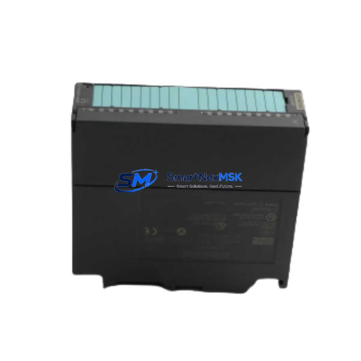
Siemens 6ES7332-7ND02-0AB0 Spare for S7-300 Automation: Spare Replacement & Industrial Downtime Risk Control
The Siemens 6ES7332-7ND02-0AB0 is an SM 332 analog output module designed for the SIMATIC S7-300 PLC platform. With 4 channels of high-resolution analog output (±10 V / 0–20 mA / 4–20 mA), this module is a critical component in process control loops, drive command interfaces, and valve positioner circuits across manufacturing, chemical, energy, and water treatment facilities. When this module fails or degrades, the downstream impact on production continuity is immediate — making a verified, tested replacement spare an essential part of any maintenance strategy.
Sourced as an original Siemens spare, each unit undergoes pre-shipment functional verification covering channel output accuracy, isolation integrity, and backplane communication. A 12-month warranty is included with every shipment, supporting both planned maintenance cycles and emergency replacement scenarios.
Spare Maintenance Table
| Parameter | Specification |
|---|---|
| SKU / Part Number | 6ES7332-7ND02-0AB0 |
| Module Type | SM 332 Analog Output Module |
| Series / Platform | SIMATIC S7-300 |
| Output Channels | 4 channels (voltage & current selectable) |
| Output Range | ±10 V, 0–20 mA, 4–20 mA, ±20 mA |
| Resolution | 13-bit (including sign bit) |
| Supply Voltage | DC 24 V (via backplane bus) |
| Load Impedance (Voltage) | ≥ 1 kΩ |
| Load Impedance (Current) | ≤ 600 Ω |
| Isolation | Channel-to-backplane isolated |
| Operating Temperature | 0 °C to +60 °C |
| Mounting | S7-300 DIN rail, standard backplane slot |
| Compatibility | S7-300 CPU 312–319, ET 200M IM 153-x |
| Origin | Germany (Original Siemens) |
| Weight | 260 g |
| Warranty | 12 Months |
| Pre-Shipment Test | Channel output, bus communication, isolation check |
Maintenance Planning for Continuous Operation
When a 6ES7332-7ND02-0AB0 is flagged for replacement during a planned shutdown or emergency callout, experienced maintenance engineers know that the analog output module rarely fails in isolation. A thorough inspection of the surrounding control cabinet and signal chain is essential to prevent repeat failures and ensure a clean return to service.
Start with the PS 307 power supply module (e.g., 6ES7307-1EA01-0AA0) — verify that DC 24 V rail voltage is within tolerance before inserting the new SM 332. Voltage sags or ripple on the supply bus are a common root cause of analog module degradation. Next, inspect the SM 321 digital input module and SM 322 digital output module in adjacent slots; backplane connector pins should be clean and free of oxidation, as poor contact resistance affects the entire rack’s signal integrity.
For the analog signal wiring, check the terminal block assemblies (such as Siemens 6ES7392-1AJ00-0AA0 front connectors) for loose terminations, insulation breakdown, or moisture ingress — particularly in environments with condensation risk. If the module drives valve positioners or variable frequency drives, confirm that the signal cable shielding is properly grounded at one end only to avoid ground loop interference.
In systems where the S7-300 rack communicates over PROFIBUS DP, verify the DP network termination resistors and cable integrity at both ends of the segment. A degraded PROFIBUS connection can cause sporadic analog output faults that are misdiagnosed as module failures. The CP 342-5 communication processor or the CPU’s integrated DP port should be checked for correct baud rate and station address configuration after any module swap.
For installations using ET 200M distributed I/O with an IM 153-x interface module, confirm that the IM firmware version is compatible with the replacement SM 332 and that the rack configuration in STEP 7 or TIA Portal matches the physical slot assignment. A configuration mismatch will prevent the CPU from recognizing the new module and trigger a hardware fault OB.
Maintenance planners should also review the SM 331 analog input module (e.g., 6ES7331-7KF02-0AB0) in the same rack — analog input and output modules in the same control loop should be treated as a paired maintenance item, especially in systems older than 8 years. Keeping a matched spare set in the local parts inventory eliminates the risk of a second unplanned outage during the same maintenance window.
Finally, for cabinets with signal isolators or loop-powered transmitters on the 4–20 mA circuits, verify isolator output compliance voltage and confirm that the total loop resistance remains within the SM 332’s specified load range. Overlooking this step after a module replacement is a frequent cause of calibration drift on the first day of resumed production.
Site Replacement Workflow
Step 1 — Isolate and document: Place the CPU in STOP mode. Record the current analog output values and process variable states for all 4 channels. Photograph the front connector wiring before removal.
Step 2 — Remove the legacy module: Disconnect the 20-pin front connector. Release the module locking screw and slide the SM 332 out of the backplane slot. Inspect the backplane connector for bent pins or contamination.
Step 3 — Prepare the replacement unit: Confirm the replacement 6ES7332-7ND02-0AB0 order number and firmware version match the project documentation. Set the measuring range jumpers (if applicable) to match the original configuration before installation.
Step 4 — Install and reconnect: Slide the new module into the correct slot. Reconnect the front connector and tighten the locking screw. Verify that the module’s RUN LED illuminates after CPU restart.
Step 5 — Functional verification: In STEP 7 or TIA Portal, force each output channel to a known value and confirm the corresponding field signal at the actuator or drive. Check for SF (system fault) or BF (bus fault) LEDs — both should be off during normal operation.
Step 6 — Return to service: Switch the CPU back to RUN mode. Monitor the first production cycle for output stability and confirm that process variables return to setpoint within expected response time.
This workflow is compatible with both hot-swap capable ET 200M configurations and standard S7-300 rack installations requiring a full CPU stop. Estimated on-site replacement time for a prepared technician: 20–45 minutes.
Spare Parts Support FAQ
Q1: Is the 6ES7332-7ND02-0AB0 still available as a new original spare?
Yes. Despite the S7-300 series reaching its end-of-sale phase, original Siemens SM 332 modules remain available through authorized industrial spare parts channels. Each unit supplied is an original Siemens product, not a third-party substitute, and is accompanied by documentation confirming authenticity.
Q2: What is the recommended inventory quantity for a facility running multiple S7-300 racks?
Industry best practice for critical analog output modules is to maintain a minimum of one spare per 4–6 installed units, or one spare per production line — whichever is greater. For facilities with legacy S7-300 systems that are no longer under OEM service contracts, holding 2–3 units in local stock is advisable given extended lead times for new procurement.
Q3: How is compatibility verified before shipment?
Each 6ES7332-7ND02-0AB0 unit is tested for backplane bus communication, per-channel analog output accuracy across all configured ranges, and channel-to-bus isolation. The order number and firmware label are verified against the Siemens product database prior to packaging. A test report is available upon request for quality-critical applications.
Q4: What does the 12-month warranty cover?
The 12-month warranty covers manufacturing defects, functional failure under normal operating conditions, and any discrepancy between the supplied unit and the stated specifications. It does not cover damage resulting from incorrect installation, overvoltage events, or environmental conditions outside the module’s rated operating range. Warranty claims are processed with priority turnaround to minimize production impact.
© 2026 SMARTNEXMSK. All rights reserved.
Original Source: https://smartnexmsk.com
Contact: [email protected] | +86 18259474341



