
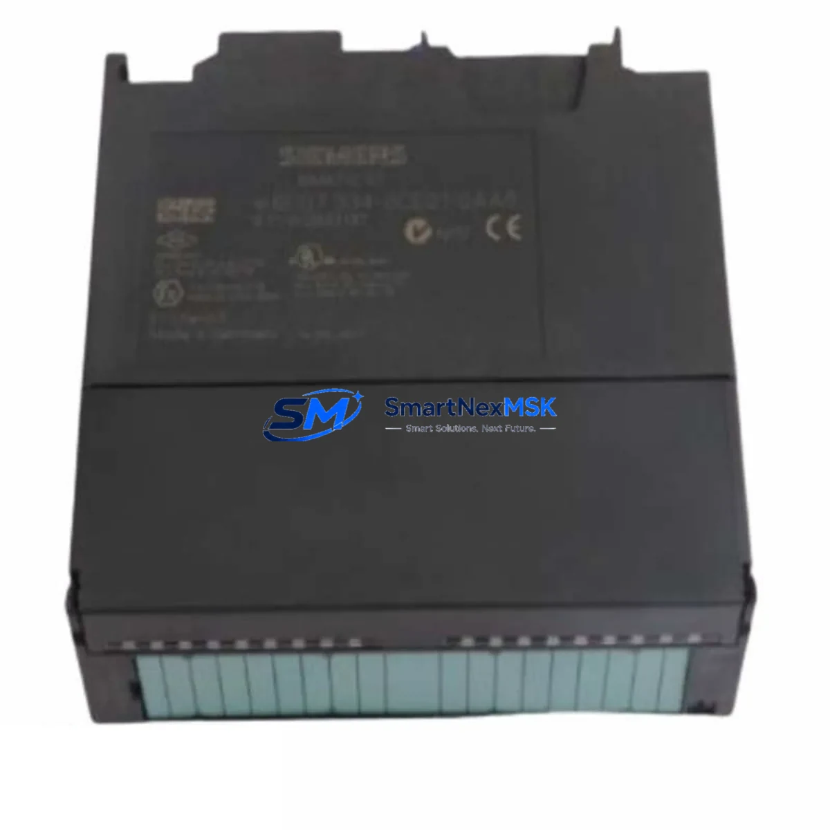
Siemens 6ES7334-0CE01-0AA0 SM334 Retrofit-Ready Analog I/O for S7-300 Control Systems
The Siemens 6ES7334-0CE01-0AA0 is the SM 334 analog input/output module designed for the SIMATIC S7-300 programmable logic controller platform. As legacy S7-300 systems approach end-of-life and original spare parts become increasingly scarce, this module serves as a critical retrofit component for engineers tasked with maintaining, upgrading, or migrating aging control architectures. Whether you are replacing a failed unit on an active production line, modernizing a control cabinet, or bridging an S7-300 system toward a phased S7-1500 migration, the 6ES7334-0CE01-0AA0 provides the analog signal handling capability required to keep your process running without interruption.
This module supports 4 analog inputs and 2 analog outputs, operating across standard industrial signal ranges including 0–10 V, ±10 V, 0–20 mA, and 4–20 mA. It mounts directly onto the S7-300 DIN rail rack and communicates via the S7-300 backplane bus, making it fully compatible with existing CPU modules such as the CPU 314, CPU 315-2 DP, and CPU 317-2 PN/DP without requiring hardware modifications to the rack or power supply wiring.
Upgrade Compatibility Table
| Parameter | Details |
|---|---|
| SKU / Part Number | 6ES7334-0CE01-0AA0 |
| Module Type | SM 334 Analog Input/Output |
| Compatible Platform | SIMATIC S7-300 |
| Analog Inputs | 4 × AI (0–10 V / ±10 V / 0–20 mA / 4–20 mA) |
| Analog Outputs | 2 × AO (0–10 V / 0–20 mA) |
| Backplane Interface | S7-300 internal bus (P-bus) |
| Installation | DIN rail, S7-300 standard rack (e.g. UR1, UR2) |
| Power Supply Compatibility | PS 307 (2A / 5A / 10A) — verify rail load budget |
| Communication Compatibility | MPI, PROFIBUS DP (via CPU), PROFINET (via CPU 317-2 PN/DP) |
| Replacement Recommendation | Direct drop-in for failed or EOL SM 334 units; verify slot address in HW Config |
| Commissioning Note | Re-download HW Config after slot insertion; verify AI/AO scaling in OB1/FC blocks |
| Warranty | 12 Months — covers manufacturing defects and functional failure |
Retrofit Planning for Existing Automation Systems
Successful integration of the 6ES7334-0CE01-0AA0 into an existing S7-300 control system requires a structured approach to hardware verification and software validation. Before removing the failed module, document the terminal wiring layout using the existing front connector — the SM 334 uses a 20-pin removable front connector that can be transferred directly to the replacement unit, preserving field wiring and reducing reconnection errors during a live changeover.
Verify the rack slot assignment in STEP 7 HW Config or TIA Portal (when using legacy import). The module address is determined by its physical slot position on the UR1 or UR2 rack, and any mismatch between the configured slot and the physical installation will generate a hardware fault on the CPU. If the system uses a CP 342-5 PROFIBUS communication processor or a CP 343-1 Industrial Ethernet module in adjacent slots, confirm that the rack’s total current draw remains within the capacity of the installed PS 307 power supply module — typically 5A or 10A variants are used in multi-module cabinets.
For systems where the S7-300 CPU communicates with a SIMATIC HMI TP700 Comfort or KTP900 Basic panel via MPI or PROFINET, verify that analog tag addresses referenced in the HMI project still map correctly after the module swap. If the original module was configured with a non-default I/O address range, the HMI screen variables may require re-linking in WinCC Flexible or TIA Portal HMI editor before the panel is restarted.
In systems undergoing a phased migration toward the S7-1500 platform, the 6ES7334-0CE01-0AA0 is commonly used as a bridge module to maintain analog I/O continuity while the CPU and communications infrastructure are upgraded. During this transition, engineers often retain the existing SM 321 digital input modules and SM 322 digital output modules on the original rack while replacing only the CPU with a CPU 1515-2 PN via an ET 200MP distributed I/O station — a strategy that minimizes rewiring and preserves field device connections. The analog signals handled by the SM 334 can be migrated to an AI 8×U/I/RTD/TC ST module on the ET 200MP rack once the process allows a scheduled shutdown.
For facilities running PROFIBUS DP networks, the existing IM 360/361 interface modules used for multi-rack expansion should be inspected for firmware compatibility when the CPU is updated. The 6ES7334-0CE01-0AA0 itself is passive on the backplane bus and does not require firmware updates, making it one of the lowest-risk components to replace during a system modernization project.
Downtime Control During System Migration
Minimizing unplanned downtime during an analog I/O module replacement begins with pre-staging the 6ES7334-0CE01-0AA0 before the maintenance window. Confirm the replacement unit powers up correctly on a bench test rack using a spare PS 307 5A power supply and a test CPU such as a CPU 314C-2 DP, verifying that all four analog input channels read correctly against a calibrated signal source and that both analog output channels drive the expected voltage and current ranges.
During the actual swap, place the CPU in STOP mode before removing the front connector from the failed module. Transfer the front connector — with all field wiring intact — directly to the replacement SM 334. After physical installation, switch the CPU back to RUN mode and monitor the diagnostic buffer for any hardware fault entries. In most cases, if the slot address and HW Config match, the CPU will recognize the new module within one scan cycle and resume normal operation without requiring a program download.
If the system uses a SIMATIC WinCC SCADA server connected via OPC DA or OPC UA, verify that the analog tag values resume updating correctly after the module is recognized. For critical process loops — such as PID controllers using analog feedback from the SM 334 inputs — confirm that the controller output is within expected range before returning the loop to automatic mode. Keep the original failed module on-site until the replacement has completed at least one full production cycle, as this provides a reference for wiring verification and fault diagnosis if unexpected behavior is observed.
Retrofit Support FAQ
Q1: Is the 6ES7334-0CE01-0AA0 a direct replacement for other SM 334 variants?
The 6ES7334-0CE01-0AA0 is the standard SM 334 AI4/AO2 × 8/8-bit variant. It is not pin-compatible with the SM 334 AI4/AO2 × 12-bit variant (6ES7334-0KE00-0AB0), which offers higher resolution. Verify your existing HW Config to confirm the correct variant before ordering. If your application requires 12-bit resolution on analog outputs, the 0KE00 variant must be used instead.
Q2: Can this module be commissioned without a STEP 7 license?
Physical installation and basic I/O operation can be verified without STEP 7 if the CPU already has a valid HW Config downloaded that includes the SM 334 in the correct slot. However, any change to the module’s slot position, I/O address range, or signal type configuration requires STEP 7 (v5.5 or later) or TIA Portal with S7-300 legacy support to modify and re-download the hardware configuration.
Q3: What wiring checks are required before powering up the replacement module?
Confirm that the front connector pin assignments match the original wiring diagram — particularly the analog input sense lines (M+ and M−) and the analog output load connections. Verify that the shield ground connections are intact and that no field wiring has been reversed during the connector transfer. Use a multimeter to confirm signal continuity on each channel before switching the CPU to RUN mode.
Q4: What does the 12-month warranty cover?
The 12-month warranty covers manufacturing defects and functional failure under normal operating conditions. Each unit undergoes pre-shipment functional testing across all analog input and output channels. The warranty does not cover damage resulting from incorrect wiring, overvoltage conditions, or installation in environments outside the module’s rated operating temperature range (0–60 °C). Contact our sales team with your order reference for warranty claims or advance replacement requests.
© 2026 SMARTNEXMSK. All rights reserved.
Original Source: https://smartnexmsk.com
Contact: [email protected] | +86 18259474341



