
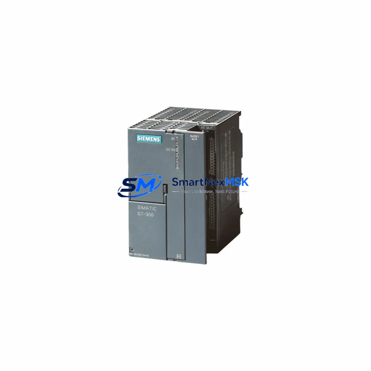
Siemens 6ES7365-0BA01-0AA0 Retrofit-Ready IM365 for S7-300 Control Systems: Compatible Modernization & Smooth Rack Expansion Upgrade
The Siemens 6ES7365-0BA01-0AA0 is the IM 365 interface module designed for the SIMATIC S7-300 programmable logic controller platform, enabling seamless rack expansion between a central rack (CR) and a single expansion rack (ER). As legacy S7-300 installations age and original spare parts become increasingly scarce, the 6ES7365-0BA01-0AA0 has become a critical retrofit component for engineers tasked with keeping existing production lines operational, extending system life cycles, and bridging the gap toward full platform migration.
Whether you are replacing a failed IM 365 in an active production environment, upgrading a control cabinet that originally ran on an older SIMATIC S7-300 configuration, or planning a phased migration toward the S7-1500 platform, this module provides the electrical and mechanical compatibility required for a reliable, low-risk retrofit. It is fully compatible with standard S7-300 mounting rails, accepts the same 24 VDC backplane power supply architecture, and communicates over the proprietary K-bus backplane interface shared across the S7-300 module family.
Upgrade Compatibility Table
| Parameter | Details |
|---|---|
| SKU / Part Number | 6ES7365-0BA01-0AA0 |
| Module Type | IM 365 Interface Module (Send + Receive pair) |
| Compatible Platform | SIMATIC S7-300 (CR + single ER configuration) |
| Backplane Interface | K-bus (S7-300 proprietary backplane) |
| Power Supply Compatibility | 24 VDC via PS 307 (6ES7307-series) or equivalent S7-300 PSU |
| Max Expansion Distance | 1.0 m (between CR and ER via included connecting cable) |
| Installation Requirement | Standard S7-300 DIN rail; slot 1 of CR and slot 1 of ER |
| Communication Compatibility | Transparent K-bus extension; no additional configuration required in STEP 7 or TIA Portal |
| Replacement Recommendation | Direct drop-in for failed or end-of-life 6ES7365-0BA01-0AA0 units |
| Commissioning Note | Verify slot addressing and I/O module addresses after replacement; re-download hardware configuration if required |
| Warranty | 12-Month Warranty included |
Retrofit Planning for Existing Automation Systems
When planning a retrofit around the 6ES7365-0BA01-0AA0, engineers must account for the full scope of the existing rack architecture. In a typical S7-300 installation, the central rack houses the CPU — commonly a CPU 315-2 DP (6ES7315-2AH14-0AB0) or CPU 317-2 PN/DP (6ES7317-2EK14-0AB0) — alongside the power supply module and up to eight I/O or function modules. The IM 365 send module occupies slot 1 of the central rack, while the matching receive module occupies slot 1 of the expansion rack, allowing the CPU to address modules in the ER as if they were locally installed.
Before replacing the 6ES7365-0BA01-0AA0, technicians should document the existing hardware configuration using STEP 7 (Simatic Manager) or TIA Portal, noting the assigned module addresses for each SM 321 digital input module, SM 322 digital output module, SM 331 analog input module, and SM 332 analog output module installed in the expansion rack. These addresses are critical for ensuring that the replacement IM 365 does not disrupt the I/O mapping expected by the existing PLC program.
Power budget verification is equally important. The PS 307 5A (6ES7307-1EA01-0AA0) or PS 307 10A (6ES7307-1KA02-0AA0) power supply modules must provide sufficient current for all modules in both racks. The IM 365 itself draws current from the backplane, and adding or replacing modules during a retrofit can shift the total load. Always recalculate the power budget before finalizing the retrofit bill of materials.
For installations that include CP 343-1 (6GK7343-1EX30-0XE0) Ethernet communication processors or CP 342-5 PROFIBUS modules, verify that the communication configuration stored in the CPU’s hardware configuration remains intact after the IM 365 replacement. In most cases, the communication modules are installed in the central rack and are unaffected by the IM 365 swap, but any changes to slot assignments in the expansion rack must be reflected in the hardware configuration and re-downloaded to the CPU.
If the retrofit involves upgrading from an older S7-300 rack to a newer mounting rail or replacing aging SM 300-series I/O modules with current production equivalents, consider whether the existing MPI/PROFIBUS programming cable (PC Adapter USB, 6ES7972-0CB20-0XA0) is compatible with the engineering workstation’s operating system. TIA Portal V17 and later versions support direct USB connection without legacy adapter requirements, simplifying the commissioning workflow.
For control cabinets that also include SIMATIC HMI panels — such as the TP700 Comfort (6AV2124-0GC01-0AX0) or OP 177B — verify that the HMI project’s tag connections reference the correct PLC data blocks and I/O addresses after the retrofit. HMI screen updates may be required if I/O module slot assignments change during the rack expansion upgrade.
Downtime Control During System Migration
Minimizing unplanned downtime is the primary concern in any S7-300 retrofit involving the 6ES7365-0BA01-0AA0. The recommended approach is to pre-stage the replacement module and verify its physical condition and firmware compatibility before scheduling the maintenance window. Because the IM 365 operates as a matched send/receive pair, both modules should be replaced simultaneously if either shows signs of failure — ordering a single unit when both are aging increases the risk of a second failure shortly after the first replacement.
Before powering down the rack, upload the current hardware configuration and PLC program from the CPU to the engineering workstation using STEP 7 or TIA Portal. Store a backup of the program blocks, hardware configuration, and any force tables or diagnostic buffers. This ensures that if the CPU loses its program during the power cycle — which can occur if the backup battery (6ES7971-0BA00-0AA0) is depleted — the program can be restored immediately without delay.
During the physical swap, label all field wiring connections to the I/O modules in the expansion rack before disconnecting any terminals. Use the existing wiring diagrams as a reference, but always verify against the physical installation, as field modifications may not be reflected in older documentation. After reinstalling the IM 365 modules and reconnecting the expansion cable, power up the system and verify that the CPU transitions to RUN mode without hardware faults. Check the diagnostic buffer in STEP 7 or TIA Portal for any module addressing errors before releasing the system to production.
For critical processes where even brief interruptions are unacceptable, consider using a hot-standby CPU configuration (available on higher-tier S7-400 or S7-1500 platforms) as part of a longer-term migration strategy. In the interim, the 6ES7365-0BA01-0AA0 retrofit provides a cost-effective path to restoring full rack expansion capability with minimal risk to the existing control logic.
Retrofit Support FAQ
Q1: Is the 6ES7365-0BA01-0AA0 a direct replacement for older IM 365 variants?
Yes. The 6ES7365-0BA01-0AA0 is the current production revision of the IM 365 and is backward compatible with earlier hardware revisions used in S7-300 installations. No hardware configuration changes are required in STEP 7 or TIA Portal when replacing an older IM 365 with this part number, provided the slot assignments remain unchanged.
Q2: Does the replacement module require any special wiring or terminal adaptation?
No additional wiring adaptation is required. The IM 365 connects to the expansion rack via the included 1-meter connecting cable, which plugs directly into the interface connectors on both the send and receive modules. Field wiring to I/O modules in the expansion rack is unaffected by the IM 365 replacement.
Q3: How is compatibility verified before shipment?
Each 6ES7365-0BA01-0AA0 unit undergoes functional testing prior to shipment, including backplane communication verification and power-on self-test. Units are shipped with original or equivalent packaging to prevent transit damage. A test report is available upon request for critical applications.
Q4: What warranty coverage is provided?
All units are covered by a 12-month warranty from the date of shipment. Warranty coverage includes replacement or repair for any defects in materials or workmanship under normal operating conditions. Our technical support team is available to assist with commissioning questions, compatibility verification, and retrofit planning throughout the warranty period.
© 2026 SMARTNEXMSK. All rights reserved.
Original Source: https://smartnexmsk.com
Contact: [email protected] | +86 18259474341



