
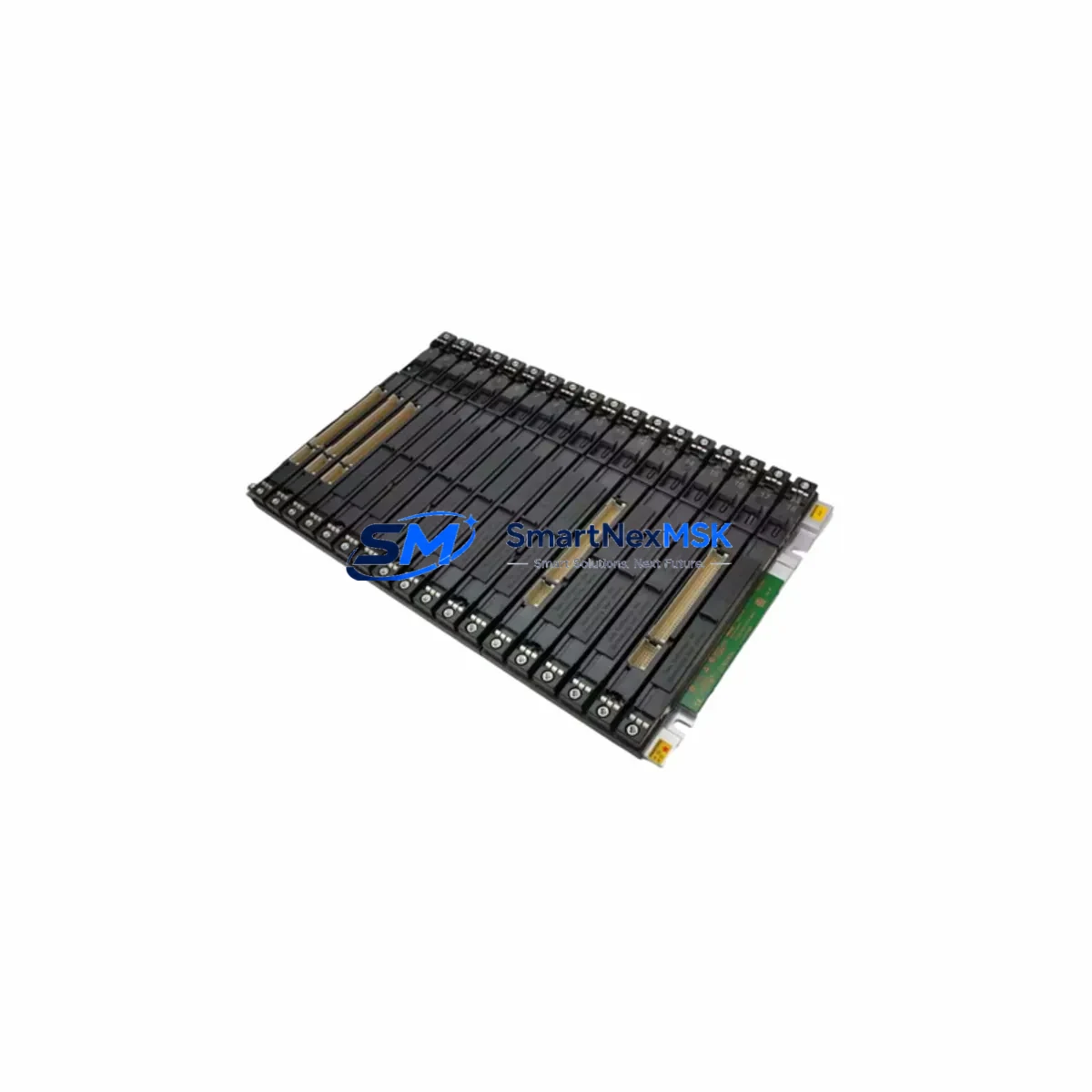
Siemens 6ES7400-1TA11-0AA0 Maintenance-Ready Spare for S7-400 Automation
The Siemens 6ES7400-1TA11-0AA0 is an original SIMATIC S7-400 rack expansion interface module designed for high-availability industrial control systems. For maintenance engineers managing aging S7-400 infrastructure, this module is a critical spare that enables rapid rack-to-rack communication restoration without system reconfiguration. Whether you are executing a planned shutdown inspection, responding to an unscheduled fault, or building a strategic spare parts inventory for a multi-rack S7-400 installation, the 6ES7400-1TA11-0AA0 delivers the compatibility and reliability required to minimize production downtime and extend the operational life of your existing control architecture.
Sourced from verified supply channels and tested prior to shipment, each unit is backed by a 12-month warranty. SMARTNEXMSK maintains long-term stock availability to support ongoing maintenance programs, ensuring you are never left waiting on a critical component during a production stoppage.
Spare Maintenance Table
| Parameter | Specification |
|---|---|
| Part Number / SKU | 6ES7400-1TA11-0AA0 |
| Brand | Siemens |
| Series | SIMATIC S7-400 |
| Module Type | Rack Expansion Interface Module (IM) |
| Function | Inter-rack communication between CR/ER racks in S7-400 systems |
| Compatible Racks | S7-400 Central Rack (CR) and Expansion Rack (ER) |
| Supply Voltage | DC 24 V (via backplane bus) |
| Transmission Rate | Up to 12 Mbit/s via PROFIBUS-based backplane |
| Max. Expansion Distance | Up to 1.5 m (send/receive IM pair) |
| Operating Temperature | 0 °C to +60 °C |
| Mounting | S7-400 rack slot (standard module form factor) |
| Origin | Germany |
| Condition | Original, new or tested-serviceable |
| Pre-shipment Test | Yes — functional verification before dispatch |
| Warranty | 12 Months |
| Delivery | Express available; DHL / FedEx / TNT |
Maintenance Planning for Continuous Operation
When replacing the 6ES7400-1TA11-0AA0 in a live S7-400 installation, a disciplined maintenance engineer will treat this as an opportunity to inspect the entire rack and inter-rack communication chain. The IM 400 send/receive pair operates in conjunction with the PS 407 power supply module — verify that the power supply is delivering stable DC 24 V and DC 5 V backplane voltage before re-seating the new interface module. A degraded PS 407 10A or PS 407 20A can cause intermittent IM faults that are misdiagnosed as module failure.
Inspect the rack backplane connectors and the inter-rack cable (typically a 368-type shielded cable) for oxidation, mechanical damage, or loose locking clips. In high-vibration environments such as press lines or compressor stations, these cables are a common failure point that accompanies IM module degradation. Replacing the IM without addressing a damaged inter-rack cable will result in recurring faults.
For the CPU side of the rack — whether a CPU 414, CPU 416, or CPU 417 — confirm that the firmware version is compatible with the IM variant installed. After module swap, perform a cold restart and monitor the diagnostic buffer in STEP 7 or TIA Portal for any rack configuration mismatch errors. If the system uses a CP 443-1 Ethernet communication processor for SCADA or MES connectivity, verify that the CP module re-establishes its connections cleanly after the rack restart.
In multi-rack configurations, also inspect the neighboring IM 460 / IM 461 send-receive pair if your installation uses extended distance expansion. Check the 24 V DC fuse on the IM power feed — a blown fuse on the terminal block or in the marshalling cabinet is a silent failure mode that prevents the IM from initializing. Terminal blocks and fuse holders in the control cabinet should be torqued to specification and inspected for heat discoloration, which indicates sustained overcurrent conditions.
For installations with analog I/O in the expansion rack, verify that SM 431 analog input modules or SM 432 analog output modules are reading correctly after the IM swap, as backplane communication interruptions can cause analog modules to latch in fault state. If your system includes ET 200M distributed I/O connected via IM 153 interface modules on a PROFIBUS DP segment, confirm that the DP master CPU re-scans and recognizes all slaves after the rack restoration. Signal isolators on 4–20 mA loops feeding the analog inputs should also be checked for drift if the rack was de-energized during the repair.
Site Replacement Workflow
Step 1 — Pre-replacement verification: Confirm the failed module is the 6ES7400-1TA11-0AA0 by checking the STEP 7 hardware diagnostics or the module LED status (SF/BF indicators). Document the slot position in the rack before removal.
Step 2 — Safe isolation: Follow your site LOTO procedure. The S7-400 rack can be powered down at the PS 407 power supply. If the system supports hot-swap on the specific rack configuration, consult the S7-400 system manual before attempting live replacement.
Step 3 — Module swap: Remove the defective 6ES7400-1TA11-0AA0 by releasing the front panel locking screws and sliding the module out of the backplane. Insert the replacement module firmly until the backplane connector is fully seated. Secure the locking screws.
Step 4 — Inter-rack cable reconnection: Reconnect the inter-rack expansion cable to both the send IM in the CR and the receive IM in the ER. Verify cable locking clips are engaged.
Step 5 — Power-up and diagnostics: Restore power at the PS 407. Observe the IM module LEDs — the green RUN LED should illuminate within 10 seconds. Open STEP 7 or TIA Portal and confirm the hardware configuration matches the physical installation. Clear any pending diagnostic alarms.
Step 6 — Functional test: Execute a controlled I/O test from the CPU to verify that all modules in the expansion rack are communicating correctly. Confirm process values are within expected ranges before returning the system to production.
This workflow is applicable as a direct replacement for the earlier 6ES7400-1TA01-0AA0 variant, maintaining full backward compatibility within the S7-400 rack system without requiring hardware configuration changes in STEP 7.
Spare Parts Support FAQ
Q1: Is the 6ES7400-1TA11-0AA0 compatible with all S7-400 rack types?
The 6ES7400-1TA11-0AA0 is designed for use in Siemens SIMATIC S7-400 central and expansion racks. It is compatible with standard S7-400 CR and ER rack configurations. Always verify your specific rack model and firmware version against the Siemens S7-400 system manual before installation. SMARTNEXMSK technical support can assist with compatibility confirmation prior to order.
Q2: How is each unit tested before shipment?
Every 6ES7400-1TA11-0AA0 unit dispatched by SMARTNEXMSK undergoes a functional verification test on a live S7-400 test bench. The test confirms backplane communication, LED status behavior, and module recognition by the CPU. A test report is available upon request. Units that do not pass functional verification are not dispatched.
Q3: What does the 12-month warranty cover?
The 12-month warranty covers manufacturing defects and functional failures under normal operating conditions as defined in the Siemens product specification. It does not cover damage resulting from incorrect installation, overvoltage events, or physical mishandling. Warranty claims are processed with a replacement-first policy to minimize your downtime.
Q4: Can SMARTNEXMSK support long-term spare parts planning for S7-400 systems?
Yes. SMARTNEXMSK maintains ongoing stock of S7-400 interface modules, power supplies, CPU modules, and I/O cards to support multi-year maintenance contracts and lifecycle extension programs for legacy S7-400 installations. Contact our team to discuss a dedicated spare parts agreement tailored to your site’s maintenance schedule.
© 2026 SMARTNEXMSK. All rights reserved.
Original Source: https://smartnexmsk.com
Contact: [email protected] | +86 18259474341



