
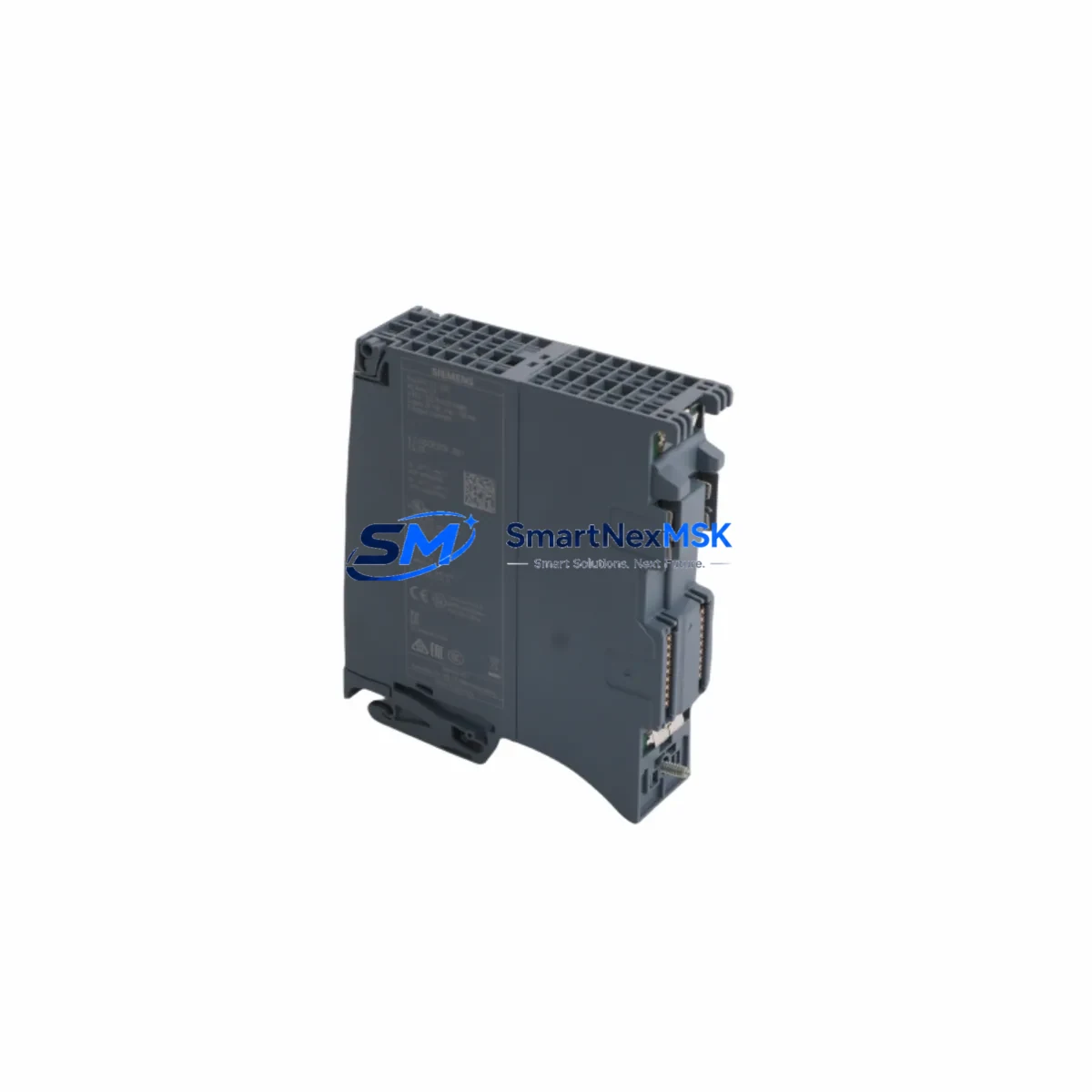
Siemens 6ES7532-5HD00-0AB0 Retrofit-Ready AQ 4×U/I ST for S7-1500 Control Systems
The Siemens 6ES7532-5HD00-0AB0 is a high-precision Analog Output Module (AQ 4×U/I ST) designed for the SIMATIC S7-1500 automation platform. As legacy S7-300 and S7-400 systems reach end-of-life and production lines demand higher throughput and diagnostic capability, the 6ES7532-5HD00-0AB0 has become a cornerstone component in control cabinet modernization projects across process automation, discrete manufacturing, and utilities sectors. SMARTNEXMSK maintains verified stock of this module with full functional testing and a 12-month warranty, enabling engineers to execute retrofit projects with confidence and minimal procurement lead time.
Upgrade Compatibility Table
| Parameter | Details |
|---|---|
| SKU / Part Number | 6ES7532-5HD00-0AB0 |
| Module Type | Analog Output, AQ 4×U/I ST |
| Compatible Platform | SIMATIC S7-1500 (all CPU variants) |
| Output Channels | 4 × Voltage (±10 V) / Current (0–20 mA, 4–20 mA) |
| Resolution | 16-bit |
| Backplane Interface | S7-1500 U-connector (direct rack mount) |
| Installation | 35 mm DIN rail or S7-1500 mounting rail |
| Communication Compatibility | PROFINET IO (via CPU), TIA Portal V13 SP1 and above |
| Common Replacement Path | S7-300 SM 332 (6ES7332-5HF00-0AB0), S7-400 AO modules |
| Retrofit Recommendation | Direct slot replacement within S7-1500 rack; address reassignment required in TIA Portal |
| Commissioning Focus | Output range configuration, wire terminal mapping, channel diagnostics enable |
| Warranty | 12 Months — functional test report available on request |
Retrofit Planning for Existing Automation Systems
Integrating the 6ES7532-5HD00-0AB0 into an existing control architecture requires a structured approach that accounts for both hardware and software dependencies. In most S7-300 to S7-1500 migration projects, the first step is auditing the existing rack configuration. Engineers typically need to account for the PS 60W 24VDC power supply module (such as the 6EP1333-4BA00) to confirm that the new analog output module’s current draw is within the rail’s capacity — the S7-1500 backplane distributes power differently from the S7-300 bus connector system.
Terminal wiring is a critical checkpoint. The 6ES7532-5HD00-0AB0 uses a 40-pin front connector (6ES7592-1AM00-0XB0), which differs from the 20-pin connectors used on legacy SM 332 modules. Field wiring from actuators — including control valves, variable frequency drives, and positioners — must be re-terminated to match the new pin assignment. It is strongly recommended to document the existing wiring diagram before disconnection and verify signal polarity for each of the four output channels.
On the software side, the module must be added to the hardware configuration in TIA Portal (V14 or later recommended). The module address in the process image must be reassigned if the slot position changes. If the legacy program used absolute addressing (e.g., PQW256), these addresses must be updated or remapped using symbolic addressing to avoid output conflicts. For projects migrating from STEP 7 Classic, the program conversion wizard in TIA Portal handles most FC/FB block translations, but analog scaling routines (FC105/FC106 equivalents) should be reviewed manually.
Communication link integrity is another key consideration. In systems where the S7-1500 CPU communicates via PROFINET IO to distributed I/O — such as ET 200SP or ET 200MP stations — the analog output module’s diagnostic alarms must be mapped correctly in the GSD/GSDML device description. If the legacy system used PROFIBUS DP with a CP 342-5 communications processor, a protocol migration to PROFINET may be required, potentially involving a PN/DP coupler or a new CP 1543-1 Ethernet module for the CPU rack.
For projects that include HMI screen updates, the tag database in SIMATIC WinCC or WinCC Comfort/Advanced must reflect the new analog output addresses. Output trend displays, faceplate controls, and alarm limits tied to the old AO module addresses will need to be updated to maintain operator visibility during and after cutover. Coordinating HMI tag migration in parallel with PLC program changes reduces the risk of blind spots during commissioning.
Downtime Control During System Migration
Minimizing production downtime during a control system retrofit is a primary engineering objective. For projects involving the 6ES7532-5HD00-0AB0, the recommended approach is a staged cutover: first install and configure the new S7-1500 rack alongside the existing system, verify all I/O mappings in simulation mode using PLCSIM Advanced, and only switch over field wiring during a planned maintenance window.
Before the cutover window, all analog output channels should be pre-tested using a loop calibrator to verify signal integrity at the field device end. The CPU 1515-2 PN or equivalent S7-1500 controller should be loaded with the converted program and placed in STOP mode. During the physical swap, the existing S7-300 rack can remain powered to maintain monitoring capability via a parallel HMI connection until the new system is confirmed stable.
Post-cutover, the module’s built-in channel diagnostics — accessible via TIA Portal online diagnostics or the CPU’s web server — provide real-time feedback on wire-break faults, short-circuit conditions, and output range violations. Enabling these diagnostics before go-live ensures that any field wiring issues are caught immediately rather than discovered during production. A structured commissioning checklist covering all four output channels, their scaling parameters, and their corresponding field device responses is essential for a clean handover to operations.
SMARTNEXMSK ships the 6ES7532-5HD00-0AB0 with a functional test report and supports pre-shipment configuration verification on request. Standard lead time from confirmed stock is 3–5 business days internationally, with express options available for urgent retrofit schedules.
Retrofit Support FAQ
Q1: Is the 6ES7532-5HD00-0AB0 a direct replacement for the S7-300 SM 332 AO 4×12Bit (6ES7332-5HD01-0AB0)?
A: It is a functional replacement in terms of channel count and output types, but it is not a mechanical drop-in — the S7-1500 uses a different rack and backplane system. A new S7-1500 mounting rail and updated TIA Portal hardware configuration are required. Signal wiring must be re-terminated to the 40-pin front connector.
Q2: What commissioning steps are required after installing this module?
A: After physical installation, add the module to the TIA Portal hardware configuration, assign the correct I/O addresses, configure output ranges per channel (voltage or current), enable channel diagnostics, download the updated configuration to the CPU, and verify each output channel with a calibrated loop tester before connecting field devices.
Q3: Can this module be used in a mixed rack with other S7-1500 I/O modules?
A: Yes. The 6ES7532-5HD00-0AB0 is fully compatible with the S7-1500 modular rack system and can be installed alongside digital input/output modules (e.g., DI 32×24VDC HF, DQ 16×24VDC/0.5A ST), other analog input modules (AI 8×U/I/RTD/TC ST), and communication modules (CM PtP, CM 1542-5) within the same rack, subject to total power budget constraints.
Q4: Does SMARTNEXMSK provide a warranty and pre-shipment testing for this module?
A: Yes. All units are covered by a 12-month warranty from the date of shipment. Each module undergoes functional output testing across all four channels prior to dispatch. A test report is available upon request. Replacement or refund is provided for any confirmed hardware defect within the warranty period.
© 2026 SMARTNEXMSK. All rights reserved.
Original Source: https://smartnexmsk.com
Contact: [email protected] | +86 18259474341



