
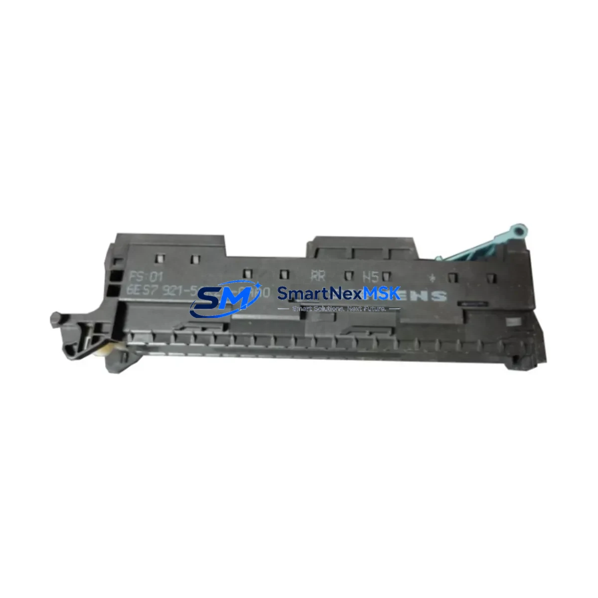
Siemens 6ES7921-5AK20-0AA0 Retrofit-Ready Front Connector for S7-300 Control Systems
The Siemens 6ES7921-5AK20-0AA0 is a 20-pin screw-type front connector designed for the SIMATIC S7-300 programmable logic controller series. As legacy S7-300 installations continue to operate across manufacturing, process control, and infrastructure sectors, this front connector remains a critical interface component for both ongoing maintenance and planned system modernization. Whether you are replacing a worn or damaged connector on an existing module, upgrading a control cabinet, or migrating from an older SIMATIC S5 platform to the S7-300 architecture, the 6ES7921-5AK20-0AA0 provides a reliable, wiring-compatible solution that minimizes retrofit complexity and reduces unplanned downtime.
This connector is compatible with a wide range of S7-300 signal modules, including digital input modules such as the SM 321 and digital output modules such as the SM 322, as well as analog input and output modules in the SM 331 and SM 332 families. The 20-pin screw terminal design accommodates field wiring directly, allowing technicians to retain existing cable harnesses during module replacement without re-terminating field wires. This is particularly valuable in retrofit scenarios where the original wiring documentation may be incomplete or where minimizing wiring changes is a priority for maintaining process continuity.
Upgrade Compatibility Table
| Parameter | Details |
|---|---|
| Part Number | 6ES7921-5AK20-0AA0 |
| Connector Type | 20-pin screw-type front connector |
| Compatible Series | SIMATIC S7-300 |
| Compatible Modules | SM 321, SM 322, SM 331, SM 332 and other 20-pin S7-300 signal modules |
| Installation Method | Direct plug-in to module front face; field wiring via screw terminals |
| Wiring Compatibility | Retains existing field wiring; no re-termination required on module swap |
| Communication Compatibility | Passive wiring interface; compatible with PROFIBUS DP and MPI backplane configurations |
| Replacement Recommendation | Direct drop-in replacement for worn, damaged, or legacy 20-pin front connectors |
| Commissioning Notes | Verify terminal torque settings; confirm module address assignment in STEP 7 or TIA Portal |
| Warranty | 12 months from date of shipment |
Retrofit Planning for Existing Automation Systems
Successful retrofit of S7-300-based control systems requires careful planning across multiple hardware and software layers. The 6ES7921-5AK20-0AA0 front connector is typically one component within a broader upgrade that may also involve the CPU module itself — for example, migrating from a CPU 314 or CPU 315-2 DP to a more capable CPU 317-2 PN/DP to support PROFINET connectivity alongside legacy PROFIBUS DP networks. In such migrations, the front connector’s wiring interface remains unchanged, which significantly reduces field labor time.
When planning a retrofit, engineers should audit the existing rack and backplane configuration. The S7-300 uses a modular rail system where modules are mounted on a DIN rail and interconnected via a U-connector bus. If the existing UR1 or UR2 universal rack is being retained, the 6ES7921-5AK20-0AA0 can be transferred directly from the old module to the replacement module without modification. However, if the rack itself is being replaced — for example, upgrading from a standard rail to an ET 200M distributed I/O configuration — the connector’s compatibility with the new mounting arrangement should be verified against the target module’s front connector specification.
Power supply capacity is another critical consideration. The PS 307 power supply modules commonly used in S7-300 cabinets are rated at 2A, 5A, or 10A. When adding new I/O modules or communication processors such as the CP 343-1 for Industrial Ethernet or the CP 342-5 for PROFIBUS DP master functionality, the total current draw on the 24 VDC bus must be recalculated to ensure the existing PS 307 can support the expanded configuration. If the power budget is exceeded, a higher-rated PS 307 or an additional power supply must be added before commissioning.
For systems that include IM 360 and IM 361 interface modules connecting expansion racks, the front connector wiring on I/O modules in the expansion racks must also be inspected during the retrofit. Connectors showing signs of terminal wear, insulation degradation, or loose screw torque should be replaced with new 6ES7921-5AK20-0AA0 units to ensure reliable signal integrity across the entire I/O chain. Replacement connectors should be pre-wired on the bench using the existing wiring schedule before the maintenance window begins, allowing hot-swap of the connector assembly during the planned outage.
Where HMI integration is part of the upgrade scope, the SIMATIC HMI OP7, OP17, or TP 177 panels connected via MPI or PROFIBUS DP to the S7-300 CPU should be tested for screen compatibility with any revised tag addresses resulting from module reconfigurations. If I/O module slot positions change during the retrofit, the corresponding hardware configuration in STEP 7 or TIA Portal must be updated and downloaded to the CPU before the HMI screens are validated.
Downtime Control During System Migration
Minimizing production downtime during an S7-300 retrofit requires a structured approach that separates preparation work from the actual cutover window. The majority of the work — including pre-wiring replacement front connectors such as the 6ES7921-5AK20-0AA0, updating the hardware configuration in STEP 7 or TIA Portal, compiling and testing the modified program offline, and staging replacement modules on the bench — should be completed before the planned maintenance window begins.
During the cutover, the recommended sequence is to power down the rack, remove the existing module, transfer the pre-wired front connector to the replacement module, insert the new module into the correct slot, restore power, and download the updated configuration and program to the CPU. If the CPU program has been modified, a memory card backup of the original program should be retained so that the system can be restored to its previous state if commissioning issues arise. For critical processes, a parallel run strategy — where the replacement module is installed in a spare slot and tested against live I/O signals before the original module is removed — can further reduce risk.
Communication link continuity is particularly important in systems where the S7-300 CPU acts as a PROFIBUS DP master controlling remote ET 200S or ET 200M distributed I/O stations. During the cutover, the PROFIBUS segment should be monitored using a diagnostic tool to confirm that all slave stations return to active status within the expected timeframe after the CPU restarts. Any slave stations that fail to re-establish communication should be investigated for address conflicts or cable integrity issues before the system is returned to production.
Retrofit Support FAQ
Q: Is the 6ES7921-5AK20-0AA0 a direct replacement for older S7-300 front connectors?
A: Yes. The 6ES7921-5AK20-0AA0 is a direct drop-in replacement for 20-pin screw-type front connectors used across the S7-300 signal module range. The connector plugs directly into the module front face and retains the existing field wiring without re-termination, making it suitable for both like-for-like replacement and module upgrade scenarios.
Q: Can I transfer the wired front connector from the old module to the new module?
A: Yes, this is the standard recommended practice for S7-300 module replacement. The front connector is designed to be removed from the module while retaining all field wiring, then plugged into the replacement module. This eliminates the need to re-identify and re-terminate individual field wires during the maintenance window, significantly reducing cutover time and the risk of wiring errors.
Q: What commissioning checks are required after installing a replacement front connector?
A: After installation, verify that all screw terminals are tightened to the specified torque (typically 0.5–0.6 Nm for this connector type), confirm that the module address assignment in the STEP 7 or TIA Portal hardware configuration matches the physical slot position, perform an I/O force test to validate signal continuity on all channels, and check the CPU diagnostic buffer for any hardware fault entries. For analog modules, a channel calibration check against a known reference signal is also recommended.
Q: What warranty coverage is provided?
A: All units supplied by SMARTNEXMSK are covered by a 12-month warranty from the date of shipment. Each unit undergoes pre-shipment functional testing to verify connector integrity and terminal condition. In the event of a warranty claim, replacement units are dispatched promptly to minimize impact on your production schedule. Contact our technical team at [email protected] for warranty support.
© 2026 SMARTNEXMSK. All rights reserved.
Original Source: https://smartnexmsk.com
Contact: [email protected] | +86 18259474341



