
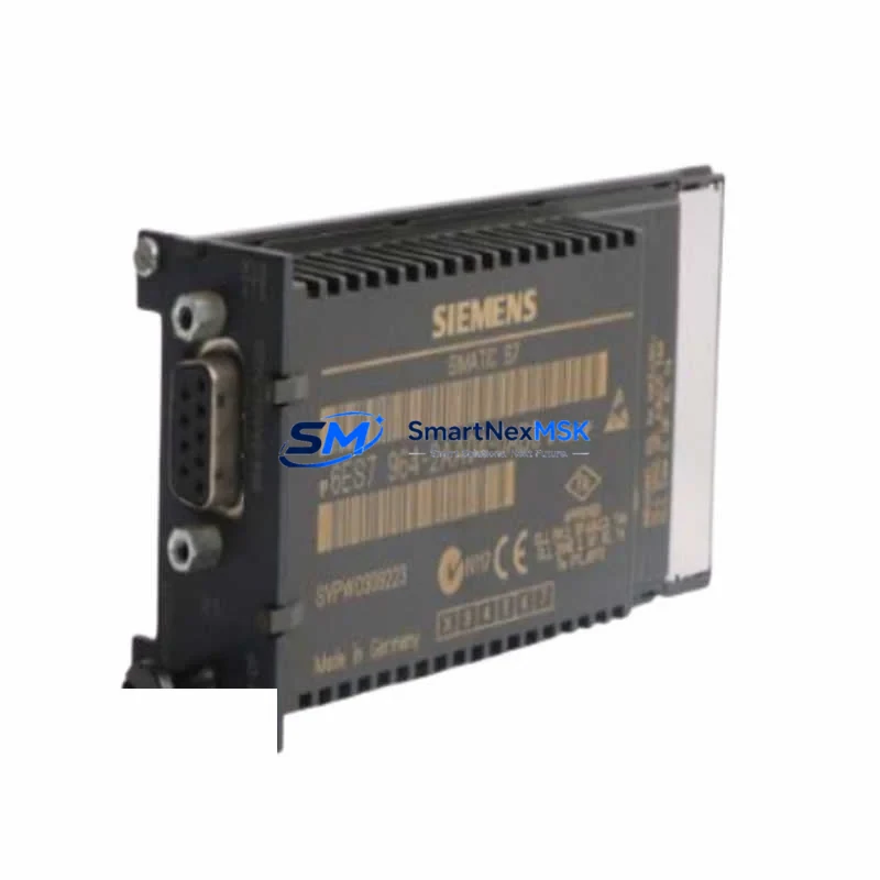
Siemens 6ES7964-2AA04-0AB0 IF964 S7-400 Spare: Spare Replacement & Industrial Downtime Risk Control
The Siemens 6ES7964-2AA04-0AB0 is the IF964 interface module designed for the SIMATIC S7-400 programmable logic controller platform. This module provides the critical rack-to-rack and S7-to-S5 communication interface that keeps legacy and hybrid automation systems running without interruption. For maintenance engineers managing aging S7-400 control cabinets, having a verified replacement unit on the shelf is not optional — it is a core element of any responsible spare parts strategy.
Whether you are performing scheduled preventive maintenance, responding to an unplanned fault, or executing a planned system upgrade from SIMATIC S5 to S7-400, the 6ES7964-2AA04-0AB0 is a direct, drop-in replacement that restores full communication capability without requiring firmware reconfiguration or hardware redesign. Its compatibility with the S7-400 backplane and standard rack mounting makes it one of the most straightforward interface module replacements in the Siemens automation portfolio.
Procurement engineers sourcing this module for long-term inventory should note that the 6ES7964-2AA04-0AB0 is a mature product in the Siemens lifecycle. Securing verified stock now — with full functional testing and a 12-month warranty — is the most cost-effective approach to protecting continuous production uptime in facilities that depend on S7-400 infrastructure.
Spare Maintenance Table
| Parameter | Specification |
|---|---|
| Part Number / SKU | 6ES7964-2AA04-0AB0 |
| Module Designation | IF964 Interface Module |
| Compatible Platform | SIMATIC S7-400 (all standard racks) |
| Communication Interface | S7-400 ↔ SIMATIC S5 / rack-to-rack link |
| Mounting | Standard S7-400 rack slot, DIN rail compatible enclosure |
| Supply Voltage | Via S7-400 backplane bus (no external power required) |
| Operating Temperature | 0 °C to +60 °C |
| Storage Temperature | -40 °C to +70 °C |
| Country of Origin | Germany |
| Product Status | Original Siemens spare — verified stock |
| Pre-shipment Testing | Full functional test performed before dispatch |
| Warranty | 12 Months from date of shipment |
| Typical Application | S5-to-S7 migration, legacy system extension, rack interface redundancy |
| Maintenance Category | Critical communication spare — recommend 1–2 units on-site stock |
Maintenance Planning for Continuous Operation
When replacing the 6ES7964-2AA04-0AB0 in a live S7-400 control cabinet, a disciplined inspection of surrounding components is essential to prevent repeat faults and ensure the replacement module operates within its rated parameters from day one.
Begin with the PS407 power supply module — verify output voltage stability under load before inserting the new interface module. A degraded power supply is a common root cause of interface module failure and will shorten the service life of any replacement unit. Alongside the power supply, inspect the S7-400 backplane bus connector for oxidation, bent pins, or mechanical damage that could cause intermittent communication errors after reinstallation.
Check the CPU 414 or CPU 416 processor module diagnostic buffer for any pre-existing fault codes related to the interface rack. If the CPU has logged repeated SF (system fault) events on the interface slot, the fault may originate upstream in the rack wiring or the IM460/IM461 send/receive interface modules used for multi-rack expansion — not solely in the 6ES7964-2AA04-0AB0 itself. Replacing the interface module without clearing these upstream faults will result in recurring alarms.
For systems that use the S7-400 in conjunction with legacy SIMATIC S5 hardware, inspect the S5-compatible connection cable (typically a 721 or 923 series cable) for insulation damage, connector wear, and correct termination resistance. A faulty cable will prevent the IF964 from establishing a stable link even after a successful module swap.
In the same maintenance window, review the ET 200M distributed I/O interface modules and any CP 443 communications processors installed in the rack. These modules share the backplane bus and can exhibit degraded performance if the interface module fault has caused bus contention. Also inspect SM 321/SM 322 digital I/O modules for blown channel fuses and verify that terminal block wiring on all I/O sub-racks is secure and correctly labeled.
Finally, if the control cabinet includes a TP 270 or OP 270 HMI panel communicating via MPI or PROFIBUS DP, confirm that the HMI connection remains stable after the interface module replacement. Communication topology changes during the swap can cause HMI address conflicts that require a soft reset to resolve. Keeping a 24 V DC signal isolator in the spare parts kit for the MPI segment is also recommended for facilities with long cable runs or high electrical noise environments.
Site Replacement Workflow
Step 1 — Pre-replacement verification: Download the current S7-400 hardware configuration from STEP 7 or TIA Portal and save a backup. Note the slot assignment of the 6ES7964-2AA04-0AB0 and confirm the replacement unit carries the same order number and firmware revision. Mismatched firmware between the IF964 and the CPU can cause configuration errors on first boot.
Step 2 — Safe removal: Place the CPU in STOP mode. Switch the rack power supply to OFF. Remove the faulty 6ES7964-2AA04-0AB0 by releasing the front panel locking screw and sliding the module out of the rack slot. Do not force the backplane connector — inspect for bent pins before inserting the replacement.
Step 3 — Installation and configuration: Insert the replacement module into the same slot. Restore rack power and switch the CPU to RUN. The IF964 does not require separate parameterization in most standard configurations — it is recognized automatically by the S7-400 CPU during startup. Verify the module status LED shows green within 30 seconds of power-on.
Step 4 — Communication verification: Confirm that the S5 link or rack-to-rack communication is re-established by checking the CPU diagnostic buffer and the connected HMI or SCADA system for active alarms. Run a short functional test cycle before returning the system to full production.
Step 5 — Documentation: Record the replacement date, module serial number, and post-replacement test results in the equipment maintenance log. Update the site spare parts inventory to trigger reorder of a replacement unit, maintaining minimum on-site stock of one module.
Spare Parts Support FAQ
Q1: Is the 6ES7964-2AA04-0AB0 a direct replacement for earlier IF964 revisions?
Yes. The -0AB0 revision is backward compatible with earlier IF964 variants in standard S7-400 rack configurations. However, always verify the hardware configuration in STEP 7 or TIA Portal to confirm slot compatibility before installation, particularly in systems running older CPU firmware.
Q2: How is the module tested before shipment?
Every 6ES7964-2AA04-0AB0 unit is subject to full functional testing on an S7-400 test rack prior to dispatch. Testing covers backplane bus communication, module recognition, and LED status verification. A test report is available on request. All units are shipped with ESD-protective packaging to prevent transit damage.
Q3: What is the recommended spare parts stocking strategy for S7-400 interface modules?
For facilities with two or more S7-400 racks in continuous production, we recommend maintaining a minimum of one IF964 module on-site at all times. For critical processes where downtime cost exceeds the module value within hours, a two-unit buffer stock is advisable. Given the mature lifecycle status of the S7-400 platform, securing verified stock now reduces exposure to future supply constraints.
Q4: What does the 12-month warranty cover?
The 12-month warranty covers manufacturing defects and functional failures under normal operating conditions from the date of shipment. It does not cover damage caused by incorrect installation, overvoltage events, or use outside the module’s rated environmental parameters. Warranty claims are processed with priority dispatch of a replacement unit to minimize production downtime.
© 2026 SMARTNEXMSK. All rights reserved.
Original Source: https://smartnexmsk.com
Contact: [email protected] | +86 18259474341



