
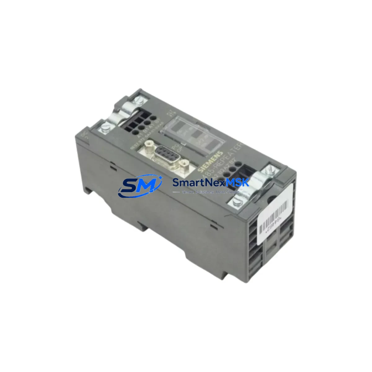
Siemens 6ES7972-0AA01-0AX0 Retrofit-Ready Interface Module for S7-300 Control Systems
The Siemens 6ES7972-0AA01-0AX0 is a PROFIBUS DP Slave Interface Module (IM306) designed for the SIMATIC S7-300 series. As legacy S7-300 installations approach end-of-life and spare parts become increasingly scarce, this module serves as a verified drop-in replacement and retrofit solution for engineers managing aging distributed I/O racks, remote expansion stations, and multi-rack control cabinet configurations. Whether you are restoring a failed node in a running production line or executing a planned upgrade of an ET 200M remote I/O station, the 6ES7972-0AA01-0AX0 provides the interface continuity required to maintain PROFIBUS DP communication without reprogramming the master CPU.
This module connects an ET 200M slave station to a PROFIBUS DP master — typically a CPU 315-2 DP, CPU 317-2 DP, or a CP 342-5 communications processor — at baud rates up to 12 Mbit/s. It supports up to 8 signal modules per slave station, making it compatible with a wide range of SM 321 digital input, SM 322 digital output, SM 331 analog input, and SM 332 analog output modules already installed in the field. The IM306 mounts directly onto a standard S7-300 DIN rail rack (e.g., UR2 or UR1 backplane) and requires no additional bus connectors beyond the standard PROFIBUS DB9 plug.
For retrofit projects, engineers must verify several critical parameters before swapping the module. First, confirm the 24 VDC supply capacity at the local power supply module — typically a PS 307 5A or PS 307 10A — as the IM306 draws from the backplane bus. Second, review the PROFIBUS DP station address configured via the rotary switch on the module face; this address must match the GSD file entry in STEP 7 HW Config or TIA Portal’s device configuration. Third, inspect the existing PROFIBUS cable segment for correct termination resistors at both ends of the segment, particularly if the ET 200M station is at a physical cable endpoint. Incorrect termination is a leading cause of intermittent communication faults after module replacement.
When integrating the 6ES7972-0AA01-0AX0 into an existing STEP 7 project, no hardware reconfiguration is required if the replacement module carries the same order number and firmware revision. The CPU will recognize the slave station on the next power cycle or PROFIBUS restart. For projects migrating from an older IM360/IM361 multi-rack expansion setup to a PROFIBUS DP distributed architecture, the IM306 simplifies the topology by eliminating the need for dedicated expansion cables between racks, reducing wiring complexity and improving fault isolation.
In control cabinet upgrade scenarios where the original S7-300 rack is being retained but the CPU is being replaced — for example, upgrading from a CPU 314 to a CPU 315-2 DP to gain PROFIBUS master capability — the IM306 allows existing remote I/O stations to remain in service without hardware changes. This is particularly valuable in food processing, water treatment, and discrete manufacturing environments where downtime windows are measured in hours, not days.
Upgrade Compatibility Table
| Parameter | Details |
|---|---|
| Module Type | PROFIBUS DP Slave Interface Module (IM306) |
| Compatible Rack | S7-300 UR1, UR2 DIN Rail Backplane |
| Communication Protocol | PROFIBUS DP (EN 50170), up to 12 Mbit/s |
| Max Signal Modules per Station | 8 (SM 321, SM 322, SM 331, SM 332) |
| Power Supply Compatibility | PS 307 5A / PS 307 10A (24 VDC backplane) |
| Station Address Setting | Rotary switch, 1–125 (must match STEP 7 / TIA Portal HW Config) |
| Replaces / Upgrades From | IM360/IM361 multi-rack expansion; legacy IM306 variants |
| Programming Software | SIMATIC STEP 7 V5.x, TIA Portal V13+ |
| Installation | DIN rail mount, no tools required |
| Commissioning Note | Verify PROFIBUS termination, station address, and GSD file version |
| Warranty | 12-Month Warranty — tested and verified before shipment |
Retrofit Planning for Existing Automation Systems
A successful retrofit begins with a complete audit of the existing PROFIBUS DP segment. Map every slave station address, confirm the GSD files loaded in the master CPU project, and document the physical cable routing and connector types. In multi-drop PROFIBUS segments, the 6ES7972-0AA01-0AX0 can be hot-swapped in some CPU configurations if the master is set to allow slave substitution — consult the CPU 315-2 DP or CPU 317-2 DP operating manual for the specific firmware behavior.
During the retrofit, engineers commonly work alongside a CP 342-5 PROFIBUS communications processor (when the base CPU lacks a DP port), a IM153-1 or IM153-2 interface module for ET 200M stations at other nodes, and SM 321 DI 16×DC 24V digital input modules that feed process signals into the rack. Analog signal chains typically involve SM 331 AI 8×12Bit modules paired with field transmitters, and output control is handled by SM 332 AO 4×12Bit modules driving control valves or variable frequency drives. For cabinet-level power distribution, the PS 307 10A power supply module must be sized to support the full backplane load including all installed signal modules.
Where HMI integration is involved — for example, a SIMATIC OP270 or TP270 panel connected via MPI — the retrofit of the IM306 does not affect the MPI network topology. HMI screen tags referencing I/O addresses in the remote ET 200M station will continue to function without modification, provided the PROFIBUS DP communication is restored correctly. For projects using WinCC flexible or TIA Portal WinCC, verify that the HMI project’s hardware configuration reflects the updated slave station parameters if any GSD file version changes are introduced.
Programming cable access during commissioning is typically via a PC Adapter USB A2 or CP 5611 card connected to the MPI port of the master CPU. Use STEP 7’s online diagnostics to confirm the IM306 slave station appears in the PROFIBUS DP master system with status “OK” before returning the line to production. Log the commissioning results, including the PROFIBUS segment scan, for the plant maintenance record.
Downtime Control During System Migration
Minimizing downtime during an IM306 replacement requires preparation before the maintenance window opens. Pre-stage the replacement 6ES7972-0AA01-0AX0 with the correct station address set on the rotary switch. Back up the STEP 7 or TIA Portal project to a memory card or engineering station. If the CPU supports it, use the “STOP” mode transition to freeze the process outputs in a safe state before removing the failed module.
Physical replacement takes under five minutes: remove the PROFIBUS connector, release the DIN rail latch, slide out the old IM306, insert the new module, reconnect the PROFIBUS plug, and power up the rack. The CPU will automatically re-establish communication with the slave station during its startup sequence. Monitor the BF (Bus Fault) LED on the IM306 — it should extinguish within seconds of a successful PROFIBUS handshake. If the BF LED remains lit, check station address, cable termination, and baud rate settings before escalating to a full segment diagnostic.
For planned migrations — such as moving from a centralized S7-300 rack to a distributed ET 200M architecture — the IM306 allows the new distributed station to be commissioned and tested on the PROFIBUS segment before the old centralized I/O is decommissioned, enabling a parallel-run validation period that protects production continuity.
Retrofit Support FAQ
Q: Is the 6ES7972-0AA01-0AX0 a direct replacement for older IM306 variants?
A: Yes. The 6ES7972-0AA01-0AX0 is the current catalog replacement for earlier IM306 order numbers. It is mechanically and electrically compatible with the same S7-300 UR1/UR2 rack slots and uses the same PROFIBUS DP interface. No changes to the STEP 7 hardware configuration are required if the order number matches the existing GSD file entry.
Q: What commissioning checks are required after installation?
A: Set the rotary station address switch to match the address configured in the master CPU project. Verify PROFIBUS cable termination at both segment ends. Power up the rack and confirm the BF LED extinguishes. Use STEP 7 online diagnostics or TIA Portal’s device view to confirm the slave station status is “OK”. Check all I/O module data in the process image before releasing the station to production.
Q: Can this module be used with TIA Portal as well as STEP 7?
A: Yes. The 6ES7972-0AA01-0AX0 is supported in both SIMATIC STEP 7 V5.x and TIA Portal V13 and later. Import the correct GSD file into the TIA Portal hardware catalog if the module does not appear automatically. The module’s behavior and parameter set are identical across both engineering environments.
Q: What does the 12-month warranty cover?
A: Every 6ES7972-0AA01-0AX0 unit is tested for PROFIBUS communication integrity, backplane bus function, and power draw before shipment. The 12-month warranty covers manufacturing defects and functional failures under normal operating conditions. Units are shipped with anti-static packaging and include a test report on request. Contact [email protected] for warranty claims or pre-shipment test documentation.
© 2026 SMARTNEXMSK. All rights reserved.
Original Source: https://smartnexmsk.com
Contact: [email protected] | +86 18259474341



