
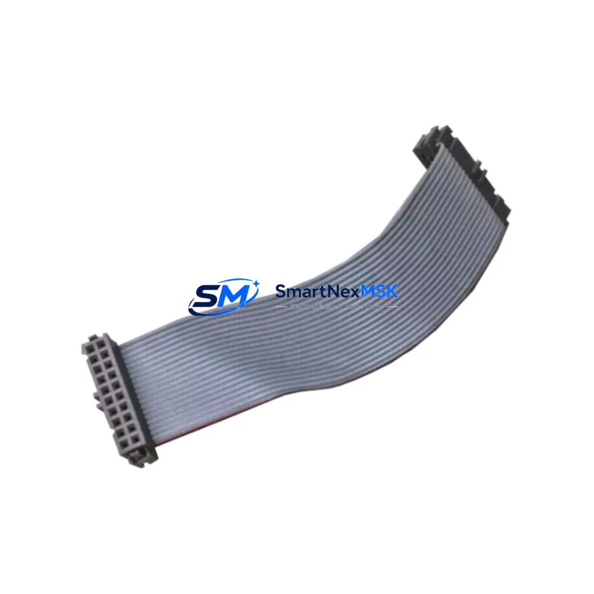
Siemens 6RY1707-0AA00 Retrofit-Ready Firing Unit for SIMOREG DC Master Control Systems
The Siemens 6RY1707-0AA00 is a firing unit board designed for the SIMOREG DC Master series of fully digital DC drive converters. As legacy SIMOREG installations approach end-of-service milestones, this component plays a critical role in extending operational life, enabling smooth retrofit transitions, and restoring discontinued drive systems without requiring a full platform migration. Whether you are replacing a failed firing board in a 6RA70 series converter or upgrading an aging DC drive cabinet, the 6RY1707-0AA00 provides a verified, compatible solution backed by 12-month warranty coverage and pre-shipment functional testing.
Upgrade Compatibility Table
| Parameter | Details |
|---|---|
| Compatible Platform | SIMOREG DC Master (6RA70 series) |
| Replaces / Fits | 6RY1707-0AA00 firing unit in 6RA7013 to 6RA7096 converters |
| Installation Type | Internal board replacement; fits standard SIMOREG converter housing |
| Communication Compatibility | Profibus-DP via CBP2 communication board; compatible with existing DP network topology |
| Terminal Wiring | Armature and field terminal assignments match original 6RY1707-0AA00 layout; no rewiring required in standard retrofit |
| Commissioning Tool | DriveMonitor or STARTER software; parameter set can be uploaded from existing drive memory |
| Replacement Recommendation | Direct drop-in for failed or degraded firing boards; verify firmware revision compatibility before installation |
| Warranty | 12 months from date of shipment; covers manufacturing defects and functional failure under normal operating conditions |
Retrofit Planning for Existing Automation Systems
Integrating the 6RY1707-0AA00 into an existing DC drive system requires a structured approach to avoid unplanned downtime and protect the integrity of the control architecture. Before beginning the retrofit, engineers should document the current parameter set using DriveMonitor connected via the RS232 port on the 6RA70 base unit or through the Profibus interface if the CBP2 communication board is installed. Saving a full parameter backup ensures that motor data, ramp times, current limits, and speed controller gains can be restored immediately after board replacement.
Power supply verification is the next critical step. The SIMOREG DC Master relies on a stable 24 VDC auxiliary supply, typically sourced from a SITOP PSU100S or equivalent regulated power supply unit within the control cabinet. Confirm that the auxiliary supply voltage is within tolerance before energizing the replacement board. Inspect the CUD1 central unit board for any fault history that may indicate upstream causes — a firing board failure is sometimes symptomatic of overvoltage transients or cooling deficiencies rather than component aging alone.
Terminal block integrity should be verified at the armature circuit connections and the field supply terminals. In older installations, the 6RA7028 or 6RA7031 converter chassis may show oxidation at screw terminals, which can cause intermittent firing faults even after board replacement. Clean and re-torque all power terminals to manufacturer specification before commissioning the new 6RY1707-0AA00.
For systems using analog speed references from a 6SE70 series inverter or a legacy PLC such as a SIMATIC S5-115U, verify that the analog input scaling on the CUD1 board matches the reference signal range. If the plant has migrated to a SIMATIC S7-300 or S7-400 controller, confirm that the Profibus DP address assigned to the SIMOREG drive is consistent with the existing hardware configuration in STEP 7 or TIA Portal. Address conflicts will prevent the drive from responding to speed commands after restart.
Where the control cabinet includes an OP17 operator panel or a SOP (Simple Operator Panel) mounted on the converter door, verify that the HMI parameter display screens still map correctly to the drive’s parameter database after the board swap. In most cases, the operator panel retains its configuration independently, but a full functional test of start, stop, speed reference, and fault reset commands from the HMI is recommended before returning the system to production.
Downtime Control During System Migration
Minimizing production interruption during a firing board replacement requires advance preparation and a disciplined commissioning sequence. Begin by scheduling the replacement during a planned maintenance window and pre-staging all required tools: insulated screwdrivers, a torque wrench calibrated to the terminal specifications, a laptop with DriveMonitor installed, and a Profibus test plug if network diagnostics are needed.
Before de-energizing the drive, record the live operating parameters — output current, armature voltage, field current, and active fault codes — from the OP17 or via DriveMonitor. This baseline data accelerates fault diagnosis if the system does not return to normal operation immediately after the board swap. Power down the converter following the SIMOREG shutdown sequence: disable the speed reference, ramp the drive to zero speed, open the main contactor, and then isolate the auxiliary 24 VDC supply before opening the converter cabinet.
After installing the 6RY1707-0AA00, restore the parameter set from the saved backup file. Perform a no-load test by enabling the drive with the motor decoupled from the mechanical load where possible. Verify that the armature current controller responds correctly to a low-speed reference before reconnecting the load. This step protects both the motor and the driven machinery from torque transients caused by incorrect current limit settings.
For systems where a full motor decoupling is not practical — such as extruder drives, winding machines, or crane hoists — use the drive’s built-in current limiting function and set a conservative speed ramp during the initial commissioning run. Confirm that the Profibus communication link is active and that the SIMATIC S7 controller is receiving valid process data words from the drive before releasing the system to automatic operation. Total planned downtime for a straightforward firing board replacement on a SIMOREG DC Master is typically two to four hours when all preparation steps are completed in advance.
Retrofit Support FAQ
Q1: Is the 6RY1707-0AA00 a direct replacement for the original firing board in all 6RA70 series converters?
The 6RY1707-0AA00 is designed for use within the SIMOREG DC Master 6RA70 platform. Compatibility depends on the specific converter size and hardware revision. Confirm the converter’s order number and hardware index before ordering to ensure the firing board variant matches your unit. Our technical team can assist with cross-referencing if you provide the full nameplate data.
Q2: Can I reuse the existing parameter set after replacing the firing board?
Yes. The parameter set is stored on the CUD1 central unit board, not on the firing board itself. Provided the CUD1 is functioning correctly, all motor data, controller settings, and communication parameters will be retained after the 6RY1707-0AA00 is replaced. A full parameter backup via DriveMonitor is still recommended as a precaution before any board-level intervention.
Q3: What pre-shipment testing is performed on the 6RY1707-0AA00?
Each unit undergoes functional verification prior to dispatch, including gate pulse output testing and insulation resistance checks. Units are shipped with protective packaging to prevent ESD damage and physical shock during transit. A 12-month warranty covers the unit against manufacturing defects and functional failure under normal operating conditions from the date of shipment.
Q4: What should I check if the drive faults immediately after installing the replacement firing board?
First, verify that the auxiliary 24 VDC supply is stable and within tolerance. Check that all ribbon cable connectors between the firing board and the CUD1 are fully seated. Review the active fault code on the OP17 or via DriveMonitor — fault F025 (firing pulse fault) or F026 (thyristor fault) typically indicates a wiring or connection issue rather than a defective board. If the fault persists after connection verification, contact our technical support team with the fault code and converter nameplate data for further diagnosis.
© 2026 SMARTNEXMSK. All rights reserved.
Original Source: https://smartnexmsk.com
Contact: [email protected] | +86 18259474341



