
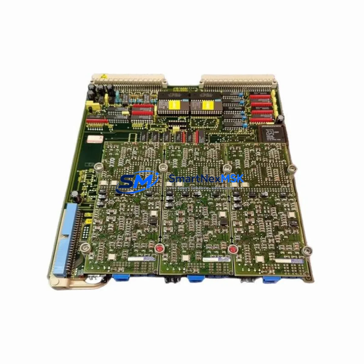
Siemens 6SC6130-0FE01 Maintenance-Ready Spare for SIMOVERT P Automation
The Siemens 6SC6130-0FE01 is an original AC Drive Power Unit designed for the SIMOVERT P variable-frequency drive series — one of Siemens’ most widely deployed drive platforms in industrial automation, process control, and motor management applications. For maintenance engineers managing aging drive cabinets, this unit represents a critical spare that enables rapid fault recovery, minimizes unplanned downtime, and extends the operational life of existing SIMOVERT P installations without requiring full system replacement.
Whether you are responding to an emergency drive fault, executing a planned overhaul, or building a strategic spare parts inventory for a multi-drive facility, the 6SC6130-0FE01 provides a verified, drop-in compatible solution backed by a 12-month warranty and pre-shipment functional testing.
Spare Maintenance Table
| Parameter | Specification |
|---|---|
| Part Number / SKU | 6SC6130-0FE01 |
| Brand | Siemens |
| Series | SIMOVERT P |
| Product Type | AC Drive Power Unit |
| Origin | Germany (DE) |
| Compatibility | SIMOVERT P series AC variable-frequency drives; drop-in replacement for equivalent power unit assemblies |
| Application Environment | Industrial automation, motor control centers, process drives, conveyor systems, pump and fan control |
| Installation | Direct module replacement; observe ESD precautions; verify bus connector alignment before seating |
| Maintenance Recommendation | Inspect cooling fans, DC bus capacitors, and gate driver boards during replacement; clean heatsink fins |
| Pre-Shipment Testing | Functional power-on test performed; results documented |
| Warranty | 12 Months from date of shipment |
| Condition | Original / Refurbished-to-spec (confirmed prior to dispatch) |
| Lead Time | In-stock units ship within 1–3 business days |
Maintenance Planning for Continuous Operation
When replacing the 6SC6130-0FE01 power unit in a SIMOVERT P drive cabinet, experienced maintenance engineers treat the event as a full cabinet health check — not just a single-component swap. The power unit interfaces directly with several adjacent assemblies, and a failure in one often signals stress or degradation in others.
Start by inspecting the SIMOVERT P control board (e.g., 6SC6130-0GE01 or equivalent) for burn marks, capacitor bulge, or corrupted parameter memory. The control board governs all drive logic and should be verified independently before the replacement unit is commissioned. Next, check the DC bus capacitor bank — capacitor aging is a primary cause of power unit failure in drives that have been in service for more than five years.
The input line filter and EMC suppression module should be inspected for signs of overheating or insulation breakdown, particularly in environments with high harmonic distortion. Alongside this, verify the condition of the braking resistor and chopper module if the drive operates in regenerative or high-inertia load applications — these components absorb energy during deceleration and are subject to thermal cycling stress.
On the I/O side, inspect the terminal strip and I/O expansion card for loose wiring, corroded terminals, or failed optocouplers. Loose connections at the control terminal block are a frequent source of intermittent faults that are misdiagnosed as power unit failures. If the drive communicates via PROFIBUS or USS protocol, confirm that the communications module (e.g., CB15 or CB11 option board) is seated correctly and that the network address and baud rate parameters are intact after the replacement.
For drives integrated with a Siemens SIMATIC S7 PLC or a DCS system, verify that the drive’s fault acknowledgment and ready signals are correctly mapped to the PLC I/O after the swap. It is also advisable to check the 24 VDC auxiliary power supply feeding the control electronics — an undersized or aging SITOP power supply can cause erratic drive behavior that mimics power unit faults.
Finally, inspect the cooling fan assembly within the drive enclosure. Fan failure is a leading cause of thermal shutdown and secondary component damage. Replacing the fan at the same time as the power unit is a low-cost, high-value preventive action. For facilities maintaining a strategic spare parts inventory, it is recommended to stock at minimum one 6SC6130-0FE01 power unit alongside a matched control board, a set of DC bus capacitors, and a spare fan assembly to cover the most common failure modes in a single maintenance event.
Site Replacement Workflow
Step 1 — Isolation and Lockout: De-energize the drive and apply LOTO (Lockout/Tagout) per site safety procedures. Allow a minimum of 5 minutes for DC bus capacitors to discharge before opening the drive enclosure. Verify bus voltage with a calibrated meter before touching internal components.
Step 2 — Parameter Backup: If the existing control board is functional, upload the drive parameters to a PC using Siemens DriveMonitor or STARTER software before removing any hardware. This preserves motor data, ramp times, and application-specific settings that would otherwise need to be re-entered manually.
Step 3 — Module Removal: Disconnect all power and signal cables from the power unit, labeling each connection. Remove the module from the drive chassis following the SIMOVERT P service manual procedure. Note the torque specifications for bus bar connections — under- or over-torquing is a common installation error.
Step 4 — Inspection and Cleaning: Before installing the 6SC6130-0FE01 replacement, clean the heatsink mounting surface and inspect the thermal interface material. Replace thermal pads if they show signs of drying or cracking. Inspect the drive enclosure for debris, moisture ingress, or rodent damage.
Step 5 — Installation and Commissioning: Seat the replacement power unit, reconnect all cables per the labeled diagram, and restore power. Perform a no-load test run before reconnecting the motor. Verify output voltage balance across all three phases. Restore parameters from backup and confirm correct operation under load before returning the drive to service.
Step 6 — Documentation: Record the replacement in the equipment maintenance log, including the date, replaced part number, new unit serial number, and any observations made during the inspection. This record supports future fault analysis and warranty claims.
Spare Parts Support FAQ
Q1: Is the 6SC6130-0FE01 a direct drop-in replacement for the original SIMOVERT P power unit?
Yes. The 6SC6130-0FE01 is designed as a direct replacement for the corresponding power unit position in the SIMOVERT P drive series. No hardware modification is required. Confirm the drive’s rated power class and voltage range match the replacement unit’s specifications before installation.
Q2: What pre-shipment testing is performed on this unit?
Each unit undergoes a functional power-on test prior to dispatch. Key parameters including DC bus voltage, gate driver output, and thermal protection circuits are verified. A test report is available upon request. Units are packed with ESD-protective materials and shock-absorbing foam to prevent transit damage.
Q3: How should I manage spare parts inventory for SIMOVERT P drives in a multi-drive facility?
For facilities operating five or more SIMOVERT P drives, we recommend maintaining at least one 6SC6130-0FE01 power unit as a hot spare. Pair this with a spare control board, a set of DC bus capacitors, and a cooling fan assembly to cover the three most common failure modes. This inventory strategy typically reduces mean time to repair (MTTR) from days to hours in the event of an unplanned drive failure.
Q4: What does the 12-month warranty cover, and how is a warranty claim initiated?
The 12-month warranty covers manufacturing defects and functional failures under normal operating conditions from the date of shipment. It does not cover damage resulting from incorrect installation, overvoltage events, or environmental contamination. To initiate a warranty claim, contact our technical support team with the order number, unit serial number, and a description of the fault. Replacement or repair will be arranged within the warranty period at no additional cost.
© 2026 SMARTNEXMSK. All rights reserved.
Original Source: https://smartnexmsk.com
Contact: [email protected] | +86 18259474341



