
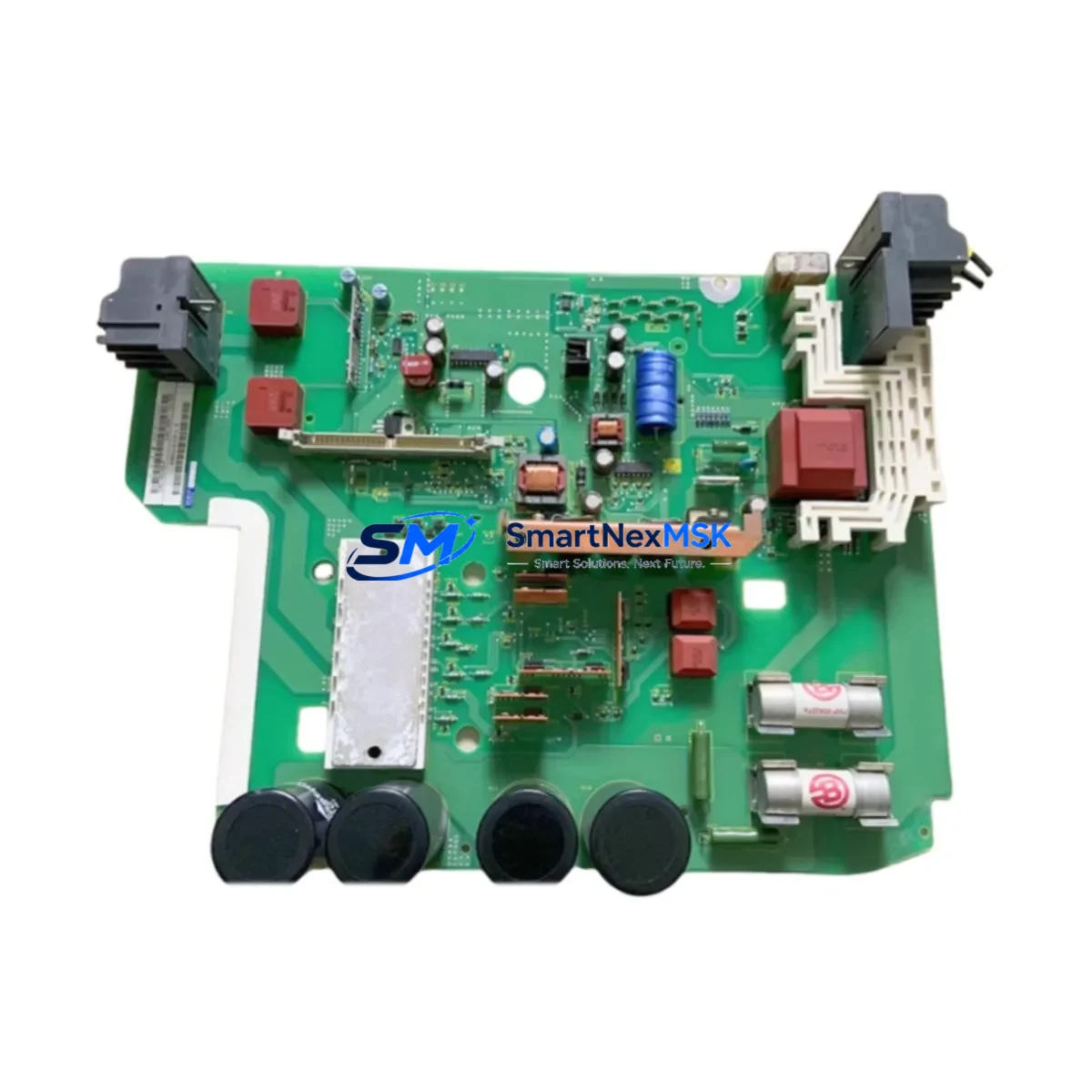
Siemens 6SE7021-3EB84-1HF3 Retrofit-Ready AC Drive for MASTERDRIVES Control Systems
The Siemens 6SE7021-3EB84-1HF3 is a 7.5 kW SIMOVERT MASTERDRIVES Vector Control AC variable frequency drive designed for demanding industrial motion control applications. As legacy MASTERDRIVES units reach end-of-service life across manufacturing plants, process lines, and material handling systems, the 6SE7021-3EB84-1HF3 serves as a verified retrofit-ready replacement that preserves existing wiring infrastructure, backplane architecture, and communication topology. Whether you are upgrading a single drive cabinet or modernizing an entire multi-axis control system, this unit delivers the electrical and mechanical compatibility required to minimize engineering rework and reduce total migration cost.
Upgrade Compatibility Table
| Parameter | Details |
|---|---|
| SKU / Part Number | 6SE7021-3EB84-1HF3 |
| Series | SIMOVERT MASTERDRIVES Vector Control |
| Power Rating | 7.5 kW (10 HP) |
| Input Voltage | 3-phase 380–480 V AC, 50/60 Hz |
| Output Current | 21.3 A nominal |
| Cooling Method | Forced air (internal fan) |
| Mounting / Form Factor | Compact chassis, DIN rail / panel mount compatible |
| Communication Interface | PROFIBUS-DP (CB15 / CBP2 option board slot) |
| Backplane / Rack Compatibility | Compatible with standard MASTERDRIVES compact and chassis rack systems |
| Replacement Recommendation | Direct replacement for discontinued 6SE70 series compact drives of equivalent power class |
| Commissioning Tool | DriveMonitor / STARTER via USS or PROFIBUS; PC adapter 6SE7090-0XX84-0KA0 |
| Parameter Migration | P-parameter sets transferable via PMU keypad or DriveMonitor backup file |
| Warranty | 12 months from date of shipment |
Retrofit Planning for Existing Automation Systems
Successful integration of the 6SE7021-3EB84-1HF3 into a legacy control cabinet begins with a thorough pre-installation audit. Engineers should verify the available DC bus capacity and confirm that the existing 6SE70 power supply module — typically a 6SE7024-7ED84-1HF3 or equivalent rectifier/regenerative unit — can sustain the combined load after the drive swap. Terminal block layouts on the 6SE7021-3EB84-1HF3 follow the standard MASTERDRIVES X9 control terminal assignment, which means existing analog setpoint wiring (0–10 V or 4–20 mA), digital input/output cabling, and relay feedback circuits can generally be reconnected without re-routing.
For systems using PROFIBUS-DP as the primary fieldbus, the CBP2 communication board installed in the option slot of the 6SE7021-3EB84-1HF3 maintains the same DP address structure as predecessor units. This allows the S7-300 or S7-400 PLC — often a CPU 315-2 DP or CPU 414-2 DP — to recognize the replacement drive without modifying the hardware configuration in STEP 7 or TIA Portal, provided the GSD file version is consistent. Where the legacy system uses USS protocol over RS-485, the existing 6SE7090-0XX84-0KA0 PC adapter cable and parameter assignment remain valid.
I/O expansion requirements should be assessed at the rack level. If the control cabinet houses a distributed I/O rack — such as an ET 200M with IM 153-2 interface module — verify that the rack’s 24 V DC backplane supply from the PS 307 power supply module is not overloaded after adding the new drive’s control circuit demand. In multi-drive cabinets, the 6SY7000-0AD87 braking resistor assembly and associated chopper module assignments must be re-verified against the updated load profile.
HMI panels connected via MPI or PROFIBUS — including OP7, OP17, or TP 177B units — typically display drive status via pre-configured variable tables linked to MASTERDRIVES parameter addresses. After replacement, confirm that the PLC data block mapping and HMI screen variable bindings still reference the correct drive node address. In most cases, no HMI reprogramming is required if the DP slave address is preserved. For systems using WinCC flexible or TIA Portal-based HMI projects, a brief online test of all drive-related faceplates is recommended before returning the line to production.
Programming cable connectivity for final parameter upload should use the 6SE7090-0XX84-0KA0 adapter or a compatible USS-to-USB converter. All parameter sets — including ramp times, current limits, motor data (P100–P115), and closed-loop PID configurations — should be backed up from the outgoing drive before removal and restored to the 6SE7021-3EB84-1HF3 using DriveMonitor’s parameter download function. Cross-check motor nameplate data against P107 (rated motor current) and P108 (rated motor speed) to ensure the auto-tuning baseline is accurate for the connected load.
Downtime Control During System Migration
Minimizing production interruption during a MASTERDRIVES drive replacement requires a structured changeover sequence. Begin by scheduling the swap during a planned maintenance window and preparing a full parameter backup of the outgoing unit. Label all control terminal wiring with permanent markers before disconnection, and photograph the terminal strip layout as a secondary reference. Pre-configure the 6SE7021-3EB84-1HF3 on a bench test rig — using a motor of equivalent rating — to validate parameter sets, ramp profiles, and fault response behavior before the unit reaches the cabinet.
On the day of changeover, isolate the drive section using the upstream MCCB or fused disconnect, discharge the DC bus fully (minimum 5 minutes after power-off, confirmed with a calibrated voltmeter), and remove the outgoing unit. Mount the 6SE7021-3EB84-1HF3, reconnect power terminals (U1/V1/W1 input, U2/V2/W2 motor output), restore control wiring to X9, and reseat the CBP2 PROFIBUS board. Power up in local mode first, confirm no fault codes on the PMU display, then transfer to remote/auto mode under PLC supervision. A controlled no-load run followed by a loaded ramp test at 25%, 50%, and 100% speed setpoints confirms stable operation before full production restart. Total planned downtime for a prepared team is typically 2–4 hours per drive position.
Retrofit Support FAQ
Q1: Is the 6SE7021-3EB84-1HF3 a direct drop-in replacement for other 6SE70 compact drives of the same power class?
Yes. The 6SE7021-3EB84-1HF3 shares the same power terminal layout, control terminal assignment (X9), and option board slot architecture as other SIMOVERT MASTERDRIVES compact units in the 7.5 kW class. Minor firmware differences may require parameter re-entry rather than a direct file restore if the source unit runs an older firmware revision.
Q2: Will my existing PROFIBUS network configuration need to be updated after replacement?
Not in most cases. Retain the same DP slave address on the CBP2 board and use the same GSD file version in your STEP 7 or TIA Portal hardware configuration. If the GSD version differs, update the configuration offline and perform a download during the maintenance window to avoid bus interruptions.
Q3: What pre-shipment testing is performed on this unit?
Each 6SE7021-3EB84-1HF3 undergoes power-on functional verification, DC bus charge/discharge cycle testing, and output phase balance checks prior to shipment. Units are shipped with protective packaging and include a test record. The 12-month warranty covers manufacturing defects and verified functional failures under normal operating conditions.
Q4: Can I reuse my existing motor cables and braking resistor wiring?
Yes, provided cable cross-sections meet the drive’s rated output current (21.3 A) and the braking resistor — such as the 6SE7021-3EB84-1HF3-compatible chopper and 6SY7000-0AD87 resistor assembly — is rated for the drive’s braking duty cycle. Inspect cable insulation and terminal crimps before reconnection, particularly in installations where the original cabling has been in service for more than five years.
© 2026 SMARTNEXMSK. All rights reserved.
Original Source: https://smartnexmsk.com
Contact: [email protected] | +86 18259474341



