
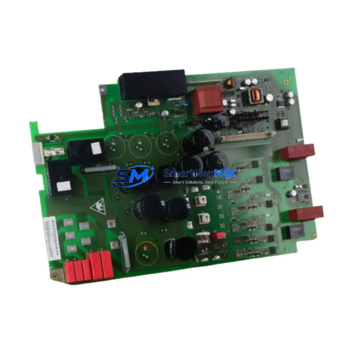
Siemens 6SE7022-6TC84-1HF3 Spare SIMOVERT MASTERDRIVES: Backup-Ready Industrial VFD Replacement
The Siemens 6SE7022-6TC84-1HF3 is a SIMOVERT MASTERDRIVES Vector Control inverter unit designed for demanding industrial drive applications. As a maintenance-ready spare, this unit supports rapid fault recovery and minimizes unplanned downtime in motor control centers, process lines, and automated manufacturing environments. Each unit supplied by SMARTNEXMSK is sourced as an original Siemens component, individually tested prior to shipment, and backed by a 12-month warranty — giving maintenance engineers and procurement teams the confidence to stock it as a critical spare.
For facilities operating SIMOVERT MASTERDRIVES MC or VC series drive systems, the 6SE7022-6TC84-1HF3 represents a direct replacement path for aging or failed inverter units. Its compatibility with the MASTERDRIVES modular architecture means it can be integrated into existing control cabinet configurations without requiring firmware re-engineering or bus reconfiguration, provided the correct option boards and firmware versions are matched during commissioning.
Spare Maintenance Table
| Parameter | Specification / Recommendation |
|---|---|
| Part Number (SKU) | 6SE7022-6TC84-1HF3 |
| Brand | Siemens |
| Series | SIMOVERT MASTERDRIVES (Vector Control) |
| Product Type | Variable Frequency Drive (VFD) / Inverter Unit |
| Rated Output Current | 22.6 A (nominal, 400 V class) |
| Power Range | ~11 kW at 400 V AC |
| Input Voltage | 3-phase AC, 380–480 V ±10% |
| Control Mode | Vector Control (VC) / Sensorless Vector |
| Communication Interface | PROFIBUS-DP (via CBP2 option board) |
| Cooling Method | Forced air cooling (internal fan) |
| Mounting | Chassis / cabinet mounting, DIN rail compatible frame |
| Country of Origin | Germany |
| Compatibility | SIMOVERT MASTERDRIVES MC/VC series; compatible with CU (Control Unit) boards and option boards of the same frame size |
| Application Environment | Industrial automation, conveyor systems, pump/fan drives, machine tools, process control |
| Maintenance Recommendation | Inspect DC bus capacitors, gate driver boards, and cooling fans every 12–18 months; replace electrolytic capacitors after 5–7 years of service |
| Warranty | 12 Months — covers manufacturing defects; each unit tested before shipment |
| Supply Condition | Original Siemens, new or refurbished-to-spec; full functional test report available on request |
Maintenance Planning for Continuous Operation
When a 6SE7022-6TC84-1HF3 inverter unit is flagged for replacement during a planned shutdown or emergency callout, experienced maintenance engineers know that the drive itself is rarely the only component requiring attention. A thorough inspection of the surrounding electrical circuit is essential to prevent repeat failures and ensure the replacement unit operates within its rated parameters from day one.
Start with the DC bus fuses and pre-charge resistors — these are often the first casualties of a hard inverter fault and must be verified before energizing a new unit. The SIMOVERT MASTERDRIVES power supply module (e.g., 6SE7024-series rectifier/infeed unit) should be checked for correct DC link voltage and ripple levels, as an unstable DC bus will stress the replacement inverter immediately. If the system uses a common DC bus architecture, inspect all parallel inverter units on the same bus for signs of thermal stress or capacitor bulging.
The Control Unit (CU) board — typically a 6SE7090-0XX84-0AB0 or equivalent — should be inspected for firmware version compatibility with the replacement power unit. Mismatched firmware between the CU and the inverter power section is a common commissioning error that leads to fault codes and failed startups. Alongside the CU, check the option board slot: if the system uses a CBP2 PROFIBUS communication board or a CBC CAN bus board, verify that the board is seated correctly and that the bus termination resistors are intact.
On the I/O side, inspect the terminal strip wiring for the analog speed reference inputs (X101/X102 terminals on standard MASTERDRIVES configurations), digital control inputs, and relay output contacts. Loose or corroded terminals at these points can cause intermittent faults that are difficult to diagnose after the drive is back online. If the system includes a Siemens OP1S operator panel or an external HMI (e.g., SIMATIC TP or MP series) for drive parameterization, confirm that the RS485/USS communication link is functional and that drive parameters have been backed up before the swap.
For motor-side protection, verify the condition of the output motor reactor (du/dt filter) and any sine-wave output filter installed between the drive and motor. These components protect motor winding insulation from high dV/dt switching transients and should be inspected for overheating or insulation breakdown. Finally, check the motor thermistor (PTC/NTC) input circuit on the CU board — a failed thermistor or open-circuit wiring here will trigger a motor overtemperature fault immediately after startup.
Stocking complementary spares alongside the 6SE7022-6TC84-1HF3 — such as a spare CU board, a CBP2 PROFIBUS option board, DC bus fuses, and a pre-charge relay — transforms a reactive maintenance posture into a proactive one, dramatically reducing mean time to repair (MTTR) for drive-related stoppages.
Site Replacement Workflow
Step 1 — Isolation and Safe State: Isolate the drive from mains supply and allow the DC bus to discharge fully (minimum 5 minutes after power-off, verify with a calibrated voltmeter at the DC bus terminals). Lock out / tag out (LOTO) per site safety procedures.
Step 2 — Parameter Backup: If the existing CU board is functional, use the OP1S operator panel or STARTER/SCOUT commissioning software to upload and save all drive parameters to a PC or memory card. This backup is critical — it allows the replacement unit to be commissioned with identical settings without re-engineering the application.
Step 3 — Physical Swap: Disconnect all power cables (L1/L2/L3 input, U/V/W motor output), DC bus links, control wiring, and option board connectors. Note cable routing and terminal labeling before removal. Install the 6SE7022-6TC84-1HF3 replacement unit, reconnect all cables in reverse order, and torque all power terminals to the specified values (refer to Siemens MASTERDRIVES installation manual, document A5E00125122).
Step 4 — Parameter Restore and Commissioning: Download the saved parameter set to the replacement unit. Verify motor data (rated voltage, current, frequency, speed, power factor) matches the connected motor nameplate. Run a motor identification routine if the motor has been replaced or if the parameter backup is unavailable.
Step 5 — Functional Test: Perform a no-load test run at low speed before reconnecting the mechanical load. Monitor DC bus voltage, output current, and drive temperature during the initial run. Confirm PROFIBUS or other fieldbus communication is re-established with the PLC (e.g., SIMATIC S7-300 or S7-400 CPU) before returning the drive to automatic control.
Step 6 — Documentation: Update the site maintenance log with the replacement date, unit serial number, and any parameter changes made. Record the removed unit’s fault history for root cause analysis.
Spare Parts Support FAQ
Q1: Is the 6SE7022-6TC84-1HF3 a direct drop-in replacement for other MASTERDRIVES units of the same frame size?
A: It is compatible within the SIMOVERT MASTERDRIVES VC/MC family at the same frame size and power rating, but compatibility must be confirmed against the existing CU board firmware version and option board configuration. Always verify the rated output current and DC bus voltage match your application before installation. SMARTNEXMSK can provide pre-shipment compatibility verification upon request.
Q2: What testing is performed before shipment?
A: Every 6SE7022-6TC84-1HF3 unit undergoes a full functional power-on test, DC bus voltage verification, gate driver integrity check, and output phase balance test before dispatch. A test report is available on request. Units are packed in anti-static, shock-protected packaging to prevent transit damage.
Q3: How should this spare be stored in a maintenance inventory?
A: Store in a dry, temperature-controlled environment (5–40°C, <95% RH non-condensing), away from direct sunlight and electromagnetic interference sources. For long-term storage exceeding 12 months, DC bus capacitors should be re-formed by applying rated voltage gradually through a variac before the unit is put into service. Inspect the unit annually for signs of corrosion or insulation degradation.
Q4: What does the 12-month warranty cover, and what is the claims process?
A: The 12-month warranty covers manufacturing defects and functional failures under normal operating conditions. It does not cover damage caused by incorrect installation, overvoltage events, or operation outside rated parameters. To initiate a warranty claim, contact SMARTNEXMSK with the unit serial number, fault description, and site installation details. Replacement or repair will be arranged within the agreed lead time.
© 2026 SMARTNEXMSK. All rights reserved.
Original Source: https://smartnexmsk.com
Contact: [email protected] | +86 18259474341



