
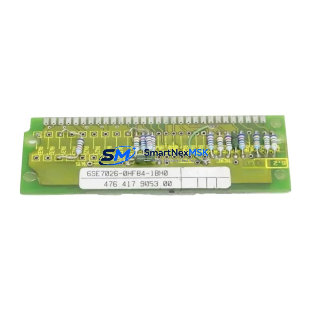
Siemens 6SE7026-0HF84-1BH0 Retrofit-Ready VFD for MASTERDRIVES Control Systems
The Siemens 6SE7026-0HF84-1BH0 is a SIMOVERT MASTERDRIVES Vector Control AC variable frequency drive designed for demanding industrial motion control applications. As legacy MASTERDRIVES units reach end-of-life or become increasingly difficult to source as original spare parts, this unit serves as a verified retrofit-ready replacement for aging production lines, control cabinet upgrades, and drive system modernization projects. Whether you are replacing a failed unit on a continuous process line or executing a planned migration from an obsolete SIMOVERT platform, the 6SE7026-0HF84-1BH0 delivers the electrical and functional compatibility required to restore or upgrade your system with minimal disruption.
This drive is rated for medium-voltage three-phase motor control and is compatible with the standard MASTERDRIVES rack and backplane architecture. Engineers undertaking a retrofit must verify the DC bus voltage, input power capacity, and output current rating against the existing installation before commissioning. Terminal wiring follows the standard MASTERDRIVES X1 power terminal layout, and the control terminal strip is compatible with the CU1 and CU2 control units commonly found in legacy MASTERDRIVES MC and VC configurations. If the existing cabinet uses a 6SE7090-0XX84-0AB0 or similar interface board, confirm connector pinout compatibility before energizing the replacement unit.
Upgrade Compatibility Table
| Parameter | Details |
|---|---|
| SKU / Part Number | 6SE7026-0HF84-1BH0 |
| Series | SIMOVERT MASTERDRIVES Vector Control |
| Typical Replacement For | 6SE7026-0HF84-0AA0, 6SE7026-0HF70-1BB0, and equivalent legacy MASTERDRIVES VC units |
| Backplane / Rack Interface | Compatible with standard MASTERDRIVES rack; verify slot address and module order |
| Communication Protocol | PROFIBUS-DP via CBP2 (6SE7090-0XX84-0FF5); USS protocol via SCB1/SCB2 optional |
| Control Terminal Compatibility | CU1 / CU2 control units; verify parameter set P060 and P070 before startup |
| Installation Requirement | DIN rail or panel mount; confirm cabinet ventilation and derating for ambient >40°C |
| Commissioning Focus | Motor data identification (P115), encoder feedback (SBP board), ramp parameters |
| Warranty | 12 months from date of shipment |
Retrofit Planning for Existing Automation Systems
A successful retrofit of the 6SE7026-0HF84-1BH0 into an existing MASTERDRIVES installation requires systematic pre-engineering. Begin by auditing the existing control cabinet for available power capacity: confirm that the incoming supply transformer and circuit breaker are rated for the drive’s input current demand, and check that the DC bus capacitor bank in the existing rectifier unit (such as the 6SE7026-0ES87-1FB0 rectifier/regenerative unit) can support the additional load if multiple drives share a common DC bus.
Terminal wiring adaptation is the next critical step. The 6SE7026-0HF84-1BH0 uses the standard MASTERDRIVES power terminal block for U1/V1/W1 input and U2/V2/W2 motor output connections. If the existing installation uses shielded motor cables with a 6SE7090-0XX84-0KA0 shield clamp kit, retain the original cable routing and grounding scheme to avoid EMC issues. The 24 VDC auxiliary supply for the control electronics must be verified against the existing 6EP1 SITOP power supply output capacity, particularly if additional I/O modules such as the T400 technology board or the SBP encoder evaluation board are installed in the same rack.
For systems that include a SIMATIC S7-300 or S7-400 PLC communicating with the drive over PROFIBUS-DP, verify that the GSD file loaded in STEP 7 or TIA Portal matches the firmware version of the replacement drive. Parameter migration from the original drive should be performed using a DriveMonitor or STARTER software backup file. If the original parameter set is unavailable, a full motor data identification run (P115 = 1) is mandatory before returning the axis to automatic mode. Systems using a SIMATIC HMI panel such as the TP177 or MP277 should have their drive parameter screens validated after commissioning to confirm that all process values, fault codes, and setpoint channels display correctly.
Where the existing system uses analog setpoint signals (0–10 V or 4–20 mA) via the CU control board’s X102 terminal strip, verify that the analog input scaling parameters (P443, P444) are correctly transferred from the original drive. Digital I/O assignments for run/stop, fault reset, and speed preset selection must also be re-confirmed against the existing PLC output card wiring, particularly if the cabinet uses a 6ES7 321 or 6ES7 322 series digital I/O module for drive control interlocks.
Downtime Control During System Migration
Minimizing production downtime during a MASTERDRIVES drive replacement requires a structured hot-swap preparation protocol. Before removing the failed or obsolete unit, use DriveMonitor or STARTER to upload and save the complete parameter set (all parameter groups including P-list and function block assignments) to a PC or USB drive. If the original drive is non-functional, retrieve the parameter backup from the PLC program or from the engineering documentation package.
Prepare the replacement 6SE7026-0HF84-1BH0 on a bench test rig before installation. Load the saved parameter set, perform a motor data identification in offline mode if possible, and verify that all digital and analog I/O assignments match the original configuration. This pre-commissioning step eliminates the majority of on-site debugging time and allows the physical swap to be completed within a single maintenance window.
During the physical installation, label all control wiring before disconnection and photograph the terminal strip layout. Retain the original motor cable and encoder cable (if a 6FX2 series encoder cable is used with an SBP board) to avoid introducing new variables. After installation, perform a controlled first-start at reduced speed setpoint with the mechanical load disconnected or at minimum load, confirm direction of rotation, and verify that all fault and warning indicators are clear before returning the drive to automatic PLC control. Maintaining a spare parameter backup file and a documented wiring diagram in the control cabinet reduces future recovery time to under two hours for trained maintenance personnel.
Retrofit Support FAQ
Q1: Is the 6SE7026-0HF84-1BH0 a direct drop-in replacement for other MASTERDRIVES VC units of the same power rating?
A: In most cases, yes — provided the replacement unit shares the same power class and control board type (CU1 or CU2). Always verify the output current rating, DC bus voltage, and firmware version. Parameter sets from the original unit must be loaded and verified before returning to service. Units with T400 technology boards or SBP encoder boards require additional configuration steps.
Q2: What communication protocols are supported, and do I need additional hardware for PROFIBUS-DP?
A: The base unit supports USS protocol via the serial interface on the CU board. PROFIBUS-DP communication requires the CBP2 option board (6SE7090-0XX84-0FF5) installed in the option slot. Confirm that the PROFIBUS address set on the CBP2 DIP switches matches the address configured in the PLC hardware configuration in STEP 7 or TIA Portal.
Q3: How do I verify wiring compatibility before energizing the replacement drive?
A: Use a continuity tester to verify that all control terminal connections match the original wiring diagram. Check that the 24 VDC auxiliary supply is within tolerance (20.4–28.8 VDC). Confirm that the motor thermistor (PTC/KTY84) is connected to the correct terminal on the CU board and that the thermistor monitoring parameter (P561) is enabled. Do not energize the power stage until all control wiring has been verified.
Q4: What does the 12-month warranty cover, and what pre-shipment testing is performed?
A: All units are function-tested prior to shipment, including power-on verification, control board communication check, and I/O signal validation. The 12-month warranty covers manufacturing defects and functional failures under normal operating conditions. Units damaged by incorrect installation, overvoltage, or environmental contamination beyond the specified IP rating are excluded. Warranty claims are processed with a return merchandise authorization (RMA) and typically resolved within 10 business days.
© 2026 SMARTNEXMSK. All rights reserved.
Original Source: https://smartnexmsk.com
Contact: [email protected] | +86 18259474341



