
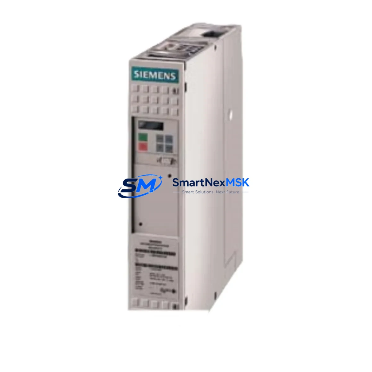
Siemens 6SE7027-2TD61-Z Retrofit-Ready VFD for MASTERDRIVES MC Control Systems
The Siemens 6SE7027-2TD61-Z G93+K11+L33 is a 75kW MASTERDRIVES MC series variable frequency drive engineered for seamless integration into existing automation infrastructures. As legacy MASTERDRIVES MC units approach end-of-life or become increasingly difficult to source, this retrofit-ready replacement offers a technically compatible upgrade path that minimizes engineering rework, preserves existing wiring layouts, and maintains control continuity across the production line.
Whether you are managing a planned system upgrade, responding to an unplanned drive failure, or executing a phased modernization of an aging control cabinet, the 6SE7027-2TD61-Z provides the electrical and mechanical compatibility required to restore operation quickly. Its G93 option enables the Safe Stop function, K11 adds the operator panel interface, and L33 provides the technology board slot — making this configuration particularly well-suited for applications that previously relied on the same option set in the original MASTERDRIVES MC platform.
Upgrade Compatibility Table
| Parameter | Details |
|---|---|
| SKU / Part Number | 6SE7027-2TD61-Z G93+K11+L33 |
| Series | Siemens MASTERDRIVES MC |
| Power Rating | 75 kW (400V AC, 3-phase) |
| Mounting / Form Factor | Chassis / booksize, compatible with original MASTERDRIVES MC rack positions |
| Communication Interface | PROFIBUS-DP via CB15 or CBP2 communication board; compatible with existing DP network topology |
| I/O Compatibility | Analog and digital I/O terminal mapping consistent with MASTERDRIVES MC standard terminal block layout |
| Option Boards | G93 (Safe Stop), K11 (Operator Panel Interface), L33 (Technology Board) |
| Replacement Scope | Direct retrofit for discontinued 6SE70 series MASTERDRIVES MC units of equivalent power class |
| Commissioning Tool | STARTER software or DriveMonitor; parameter upload/download via USS or PROFIBUS |
| Warranty | 12 months from date of shipment |
| Pre-shipment Testing | Function-tested and inspected prior to dispatch |
Retrofit Planning for Existing Automation Systems
A successful retrofit of the 6SE7027-2TD61-Z into an existing MASTERDRIVES MC installation requires careful pre-engineering across several subsystems. Before removing the legacy drive, engineers should document the full parameter set using DriveMonitor or STARTER software, capturing all P-parameters including ramp times, current limits, encoder feedback settings, and technology controller configurations stored on the L33 technology board.
The control cabinet power supply must be verified to support the inrush and steady-state current demands of the replacement unit. In many older installations, the 6EP1 series SITOP power supply modules feeding the 24VDC control bus may require capacity review, particularly where additional I/O modules or the K11 operator panel draw supplementary current. The DC bus connection and pre-charge circuit should also be inspected before energizing the new drive.
Terminal wiring compatibility is a key advantage of this replacement. The 6SE7027-2TD61-Z retains the standard MASTERDRIVES MC terminal block assignments for analog speed reference (terminals 1–4), digital enable and fault signals (terminals 5–12), and relay outputs (terminals 13–16). Engineers should cross-reference the existing wiring diagram against the replacement unit’s terminal diagram to confirm pin-for-pin compatibility before reconnection.
For systems using PROFIBUS-DP communication, the drive’s node address must be set to match the original unit’s DP address. The GSD file for the MASTERDRIVES MC drive profile should be verified in the SIMATIC S7 hardware configuration — in most cases, the existing GSD entry remains valid for the replacement unit, avoiding the need to modify the S7-300 or S7-400 hardware configuration in STEP 7. Where the control system uses a CP 342-5 or CP 443-5 PROFIBUS master module, no changes to the network configuration are typically required.
If the installation includes a SIMOVIS or OP17 operator panel connected via the K11 interface, the panel’s parameter assignments and display screens should be backed up prior to the swap. After installation, the parameter set can be restored via the K11 interface or directly through the STARTER project file. Systems that also incorporate a 6SN1 SIMODRIVE axis module or a 6RA70 series DC drive in the same control cabinet should be assessed for shared DC bus compatibility and sequencing logic in the PLC program.
Where the legacy system includes a 6ES7 series ET 200 distributed I/O rack connected to the drive’s technology board via the L33 slot, the rack configuration and module addressing should be preserved in the replacement. Any 6ES7 321 digital input modules or 6ES7 332 analog output modules mapped to the drive’s process image must retain their original slot assignments to avoid PLC program modifications.
Downtime Control During System Migration
Minimizing production downtime during a MASTERDRIVES MC drive replacement requires a structured migration sequence. The recommended approach begins with a full parameter backup of the existing drive, followed by a pre-commissioning bench test of the replacement 6SE7027-2TD61-Z using the same parameter file. This allows engineers to verify motor data, control mode, and communication settings before the unit reaches the production floor.
During the physical swap, the original control wiring should be labeled and photographed at the terminal block level before disconnection. The replacement drive should be mounted, wired, and powered up in local control mode first, confirming motor rotation direction and speed reference response before switching to PROFIBUS-DP remote control. This staged approach isolates potential wiring or parameter issues before the drive is placed under PLC control, reducing the risk of extended fault-finding during the critical restart window.
For facilities operating continuous processes, a planned maintenance window of four to six hours is typically sufficient for a like-for-like MASTERDRIVES MC replacement of this power class, assuming the parameter file is prepared in advance and the replacement unit has been pre-tested. Where the installation also requires firmware updates to the L33 technology board or reconfiguration of the G93 Safe Stop circuit, additional time should be allocated for functional safety verification in accordance with the site’s safety management procedures.
After restart, the drive should be monitored through at least one full production cycle before the maintenance window is closed, with particular attention to thermal performance, current draw relative to the original unit’s logged values, and PROFIBUS communication cycle consistency as reported by the S7 CPU diagnostic buffer.
Retrofit Support FAQ
Q: Is the 6SE7027-2TD61-Z G93+K11+L33 a direct drop-in replacement for my existing MASTERDRIVES MC unit?
A: Yes, for equivalent power class MASTERDRIVES MC installations. The terminal layout, mounting dimensions, and PROFIBUS-DP communication profile are compatible with the original platform. Minor parameter adjustments may be required to match site-specific motor data and ramp settings.
Q: Can I reuse my existing parameter file from the old drive?
A: In most cases, yes. Parameter files created with DriveMonitor or STARTER for the original MASTERDRIVES MC unit can be uploaded to the replacement drive. Parameters specific to hardware options (such as the L33 technology board configuration) should be reviewed and verified after upload.
Q: What pre-shipment testing is performed on this unit?
A: Each unit undergoes functional testing prior to dispatch, including power-on verification, communication interface check, and option board confirmation. Units are shipped with a 12-month warranty covering manufacturing defects and functional failures under normal operating conditions.
Q: What should I verify regarding the G93 Safe Stop option during commissioning?
A: The G93 Safe Stop circuit must be verified against the site’s safety wiring diagram. The STO (Safe Torque Off) input terminals should be tested for correct response before the drive is placed in automatic mode. If the original installation used a safety relay module such as the 3TK28 series, the wiring to the G93 terminals should be confirmed against the relay’s output contact assignment.
© 2026 SMARTNEXMSK. All rights reserved.
Original Source: https://smartnexmsk.com
Contact: [email protected] | +86 18259474341



