
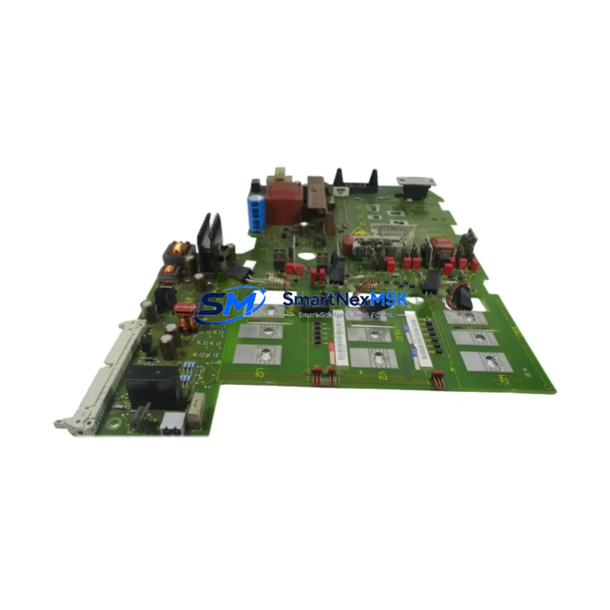
Siemens 6SE7027-2TD84-1HF4 Maintenance-Ready Spare for MASTERDRIVES MC Automation
The Siemens 6SE7027-2TD84-1HF4 is a high-performance inverter module within the SIMOVERT MASTERDRIVES MC (Motion Control) series, engineered for demanding industrial drive applications including conveyor systems, hoisting equipment, compressors, and precision motion control platforms. As a maintenance-ready original spare, this unit is sourced, inspected, and dispatched to support rapid replacement workflows — minimizing unplanned downtime and protecting production continuity in critical automation environments.
For maintenance engineers managing aging MASTERDRIVES MC installations, securing a verified replacement for the 6SE7027-2TD84-1HF4 is a cornerstone of any proactive spare parts strategy. This module covers the power stage of the drive system and interfaces directly with the control electronics, DC bus, and motor output terminals. When this component fails or degrades, the entire drive axis is lost — making fast, compatible replacement essential to restoring operation without full system redesign.
Spare Maintenance Table
| Parameter | Specification |
|---|---|
| Part Number / SKU | 6SE7027-2TD84-1HF4 |
| Brand | Siemens |
| Series | SIMOVERT MASTERDRIVES MC (Motion Control) |
| Product Type | Inverter Module |
| Rated Output Current | 27 A (nominal) |
| DC Bus Voltage | 510–650 V DC (nominal range) |
| Output Voltage | 3-phase AC, up to 400 V |
| Cooling Method | Forced air / integrated fan |
| Protection Class | IP20 (cabinet installation) |
| Mounting | Chassis / booksize format, DIN rail compatible backplane |
| Communication Interface | PROFIBUS DP via CBP2 / CBC adapter (optional) |
| Compatible Control Board | CU (Control Unit) for MASTERDRIVES MC series |
| Origin | Germany (DE) |
| Application Environment | Industrial cabinet, 0–40°C ambient, <95% RH non-condensing |
| Maintenance Recommendation | Replace DC bus capacitors every 5–7 years; inspect fan and IGBT gate drivers annually |
| Warranty | 12 Months from date of shipment |
| Dispatch | Tested before shipment; functional verification report available on request |
Maintenance Planning for Continuous Operation
When replacing the 6SE7027-2TD84-1HF4 inverter module in a MASTERDRIVES MC cabinet, a thorough maintenance inspection of the surrounding electrical system is strongly recommended. Experienced maintenance engineers know that an inverter failure is rarely an isolated event — associated components are often stressed or degraded simultaneously.
Begin with the DC bus capacitor bank and pre-charge resistor circuit: these are common failure points in aging MASTERDRIVES MC installations and should be inspected or replaced as part of any inverter module swap. Check the line reactor (input choke) for signs of overheating or insulation breakdown, as it protects the rectifier stage from line transients.
The MASTERDRIVES MC Control Unit (CU) — typically a 6SE7090-0XX84-0AB0 or equivalent — should be verified for firmware integrity and parameter backup before the inverter swap. If the CU has been running continuously for more than 5 years, consider scheduling a replacement during the same maintenance window. Similarly, the CBP2 PROFIBUS communication board (6SE7090-0XX84-2FK0) should be inspected for connector wear and address switch integrity.
On the power distribution side, verify the 24 V DC auxiliary power supply feeding the control electronics — a marginal PSU can cause erratic drive behavior that mimics inverter faults. Check the main contactor and soft-start relay in the incoming power circuit, as contact wear can introduce voltage dips that stress the inverter module. Inspect all terminal blocks and bus bar connections in the cabinet for signs of thermal cycling damage, loose torque, or oxidation.
For I/O integrity, test the analog input/output signal conditioning cards and any signal isolators used on speed reference or torque feedback circuits — degraded isolation can introduce noise that causes nuisance trips. If the system uses an encoder feedback module (such as the SBP or SBR board), verify encoder cable shielding and connector seating before commissioning the replacement inverter.
Finally, review the motor cable insulation resistance with a megger test before reconnecting to the new inverter module. A degraded motor winding or cable fault is a leading cause of premature inverter failure and must be ruled out before energizing the replacement unit.
Site Replacement Workflow
Replacing the 6SE7027-2TD84-1HF4 on-site follows a structured sequence to ensure system compatibility and minimize downtime:
1. Parameter Backup: Before de-energizing, upload the full parameter set from the existing Control Unit using STARTER or DriveMonitor software. Store the backup on a local PC and a USB drive. This ensures the replacement inverter can be commissioned with the exact same drive configuration without re-engineering.
2. Safe Isolation: Isolate the drive from the main supply and verify DC bus discharge (below 50 V DC) using a calibrated multimeter before opening the cabinet. MASTERDRIVES MC units retain DC bus charge for several minutes after power-off.
3. Module Extraction: Disconnect the DC bus connectors, motor output terminals, fan supply, and control harness in sequence. Note cable routing and label all connectors before removal. The 6SE7027-2TD84-1HF4 is a booksize chassis unit — support the module weight during extraction to avoid connector damage.
4. Replacement Installation: Install the new 6SE7027-2TD84-1HF4 module, reconnect all terminals to the original torque specifications (refer to the MASTERDRIVES MC hardware installation manual), and verify bus bar alignment before energizing.
5. Parameter Restore and Commissioning: Download the saved parameter set to the Control Unit, perform a motor identification run if required, and verify all I/O signals, speed references, and safety interlocks before returning the drive to production.
This workflow is compatible with direct replacement of older 6SE70 series inverter modules in the same power class, allowing system life extension without PLC or HMI reconfiguration.
Spare Parts Support FAQ
Q1: Is the 6SE7027-2TD84-1HF4 a direct drop-in replacement for other 6SE7027 variants?
The 6SE7027-2TD84-1HF4 is specific to the MASTERDRIVES MC series with the -1HF4 technology option package. It is not directly interchangeable with standard MASTERDRIVES VC (Vector Control) variants of the same power rating. Always verify the full part number including the technology suffix before ordering. Our team can assist with cross-reference verification prior to shipment.
Q2: What pre-shipment testing is performed on this spare?
Each unit undergoes functional power-on verification, DC bus capacitor ESR check, IGBT gate drive signal test, and visual inspection for physical damage before dispatch. A test report is available on request. Units are packed in anti-static, shock-protected packaging suitable for international freight.
Q3: How should this spare be stored in a maintenance inventory?
Store in a dry, temperature-controlled environment (5–40°C), away from direct sunlight and electromagnetic interference sources. DC bus capacitors in stored inverter modules should be re-formed every 12–18 months if the unit is not put into service. We recommend rotating spare stock on a first-in, first-out basis to maintain capacitor health.
Q4: What does the 12-month warranty cover?
The 12-month warranty covers manufacturing defects and functional failures under normal operating conditions from the date of shipment. It does not cover damage resulting from incorrect installation, overvoltage events, or operation outside rated parameters. Warranty claims are supported with a return and replacement process — contact our technical team for RMA initiation.
© 2026 SMARTNEXMSK. All rights reserved.
Original Source: https://smartnexmsk.com
Contact: [email protected] | +86 18259474341



