
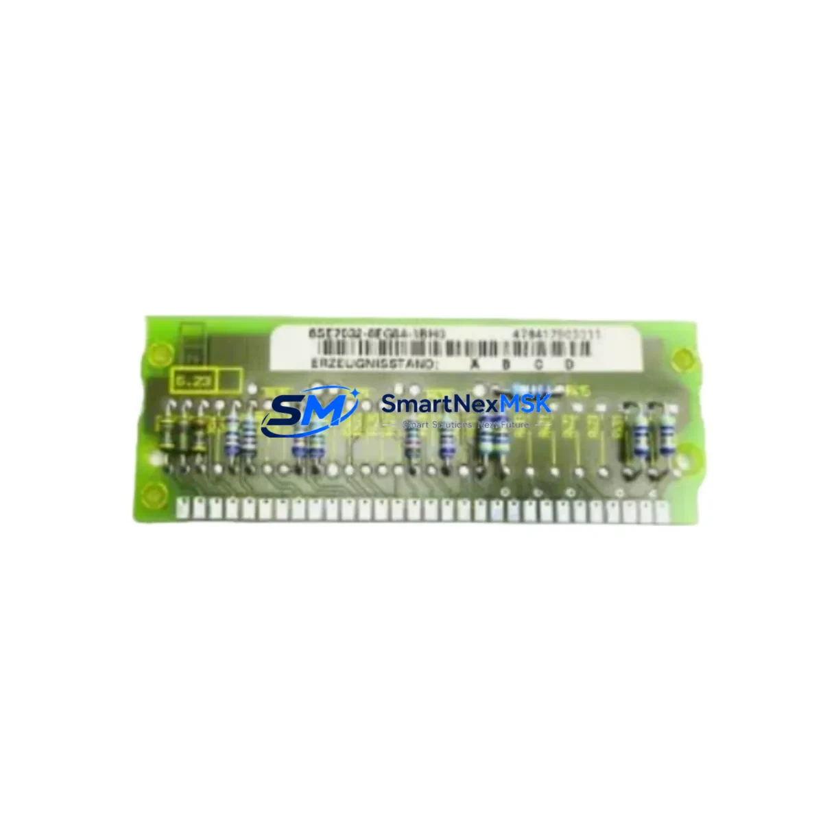
Siemens 6SE7032-6EG84-1BH0 Retrofit-Ready Inverter Module: Seamless Compatibility for Legacy MASTERDRIVES MC Control Systems
The Siemens 6SE7032-6EG84-1BH0 is a high-power inverter module rated at 160 kW, designed for the SIMOVERT MASTERDRIVES MC (Motion Control) platform. As legacy MASTERDRIVES MC installations age and original spare parts become increasingly scarce, this module serves as the definitive retrofit and replacement solution for engineers tasked with modernizing existing drive cabinets, upgrading discontinued inverter assemblies, and restoring full operational continuity to critical production lines.
Whether you are replacing a failed unit in an emergency shutdown scenario, executing a planned control system upgrade, or migrating an aging drive train to a more maintainable configuration, the 6SE7032-6EG84-1BH0 is engineered to slot into existing MASTERDRIVES MC rack assemblies with minimal re-engineering. Its compatibility with the standard MASTERDRIVES MC backplane interface, PROFIBUS-DP communication protocol, and established terminal wiring conventions means that experienced commissioning engineers can restore full drive functionality while preserving existing PLC program logic, HMI screen layouts, and field instrumentation wiring.
Upgrade Compatibility Table
| Parameter | Details |
|---|---|
| SKU / Part Number | 6SE7032-6EG84-1BH0 |
| Platform | SIMOVERT MASTERDRIVES MC (Motion Control) |
| Power Rating | 160 kW |
| Input Voltage | 3-phase AC, 380–480 V |
| Backplane Interface | Standard MASTERDRIVES MC rack slot — direct plug-in replacement |
| Communication Protocol | PROFIBUS-DP (CBP2 communication board compatible) |
| Terminal Wiring | Compatible with existing MASTERDRIVES MC terminal strip layouts |
| Replaces / Supersedes | Earlier 6SE70 series inverter modules of equivalent power class |
| Installation Requirement | Verify DC bus voltage, cooling airflow clearance, and rack slot assignment |
| Commissioning Tool | STARTER / DriveMonitor via USS or PROFIBUS; parameter set upload recommended |
| Retrofit Recommendation | Upload and verify existing parameter set (P-list) before first power-on |
| Warranty | 12 Months — covers manufacturing defects and functional failure under normal operating conditions |
Retrofit Planning for Existing Automation Systems
A successful retrofit of the 6SE7032-6EG84-1BH0 begins well before the module arrives on site. Engineers should start by auditing the existing control cabinet to confirm that the MASTERDRIVES MC rack (typically a 6SE70 series chassis) has a compatible slot available and that the DC bus rail is correctly rated for the 160 kW power class. In multi-axis installations, the shared DC bus architecture means that the Active Front End (AFE) rectifier unit — often a 6SE7033 or 6SE7035 series component — must be verified for adequate power headroom before the new inverter module is energized.
Terminal wiring should be mapped against the original cabinet drawings. The 6SE7032-6EG84-1BH0 uses the standard MASTERDRIVES MC terminal block layout, so existing motor power cables (U2, V2, W2), brake resistor connections, and control signal wiring (enable, fault reset, speed reference) typically transfer without modification. However, engineers should inspect terminal torque values and cable cross-sections to ensure compliance with the module’s input specifications.
For sites running PROFIBUS-DP networks, the CBP2 communication board installed in the inverter’s option slot must be confirmed as present and correctly addressed. The PROFIBUS node address set on the CBP2 must match the address previously assigned to the replaced unit in the SIMATIC S7 PLC configuration — typically managed via STEP 7 or TIA Portal. Failure to match the node address will result in a bus fault and prevent the drive from receiving speed setpoints or control commands from the PLC.
Where the existing system uses a SIMATIC OP or TP HMI panel for drive monitoring and fault display, engineers should verify that the HMI screen tags referencing drive parameters (output frequency, DC bus voltage, fault codes) remain valid after the module swap. In most MASTERDRIVES MC installations, HMI communication passes through the PLC rather than directly to the drive, so HMI screen logic is typically unaffected by the inverter replacement.
I/O expansion modules connected to the MASTERDRIVES MC — such as the SBP encoder evaluation board or T400 technology board — should be removed from the old module and re-installed in the replacement unit before commissioning. These option boards carry axis-specific configuration data and encoder interface settings that are critical for closed-loop speed and position control applications.
For sites that also need to address upstream power quality, the 6SE7031 series line reactor or input filter module should be inspected and replaced if showing signs of thermal stress. Similarly, if the control cabinet includes a SIMOREG DC Master for legacy DC drive axes running in parallel with the MASTERDRIVES MC inverter axes, the shared control bus wiring and interlock logic should be reviewed to ensure the retrofit does not introduce timing conflicts during startup sequences.
Finally, before closing the cabinet and returning the line to production, a full parameter upload using DriveMonitor or the STARTER commissioning tool is strongly recommended. Comparing the uploaded parameter set against the archived P-list from the original module confirms that all application-specific settings — ramp times, current limits, speed controller gains, and fault response configurations — have been correctly transferred to the replacement unit.
Downtime Control During System Migration
Minimizing unplanned downtime is the primary operational concern when replacing a 160 kW inverter module in a live production environment. The recommended approach is to pre-stage the 6SE7032-6EG84-1BH0 as a tested, pre-configured spare: load the archived parameter set from the failed unit (or from the most recent backup) into the replacement module using DriveMonitor before the scheduled maintenance window begins. This eliminates the need for on-site parameter entry during the outage and reduces the risk of commissioning errors under time pressure.
During the physical swap, the DC bus should be fully discharged and verified with a calibrated voltmeter before any module handling begins — residual DC bus voltage in a 160 kW MASTERDRIVES MC system can remain hazardous for several minutes after mains disconnection. Once the replacement module is seated in the rack and all terminal connections are verified, a controlled test run at reduced load is recommended before returning the axis to full production speed. Monitor output current, DC bus voltage, and PROFIBUS communication status during the initial run to confirm stable operation.
For critical production lines where even a brief outage is unacceptable, maintaining a pre-configured 6SE7032-6EG84-1BH0 as a hot-standby spare — with the parameter set pre-loaded and the module stored in a climate-controlled environment — is the most effective strategy for achieving sub-hour recovery times in the event of an unexpected drive failure.
Retrofit Support FAQ
Q1: Is the 6SE7032-6EG84-1BH0 a direct drop-in replacement for other 6SE7032 series modules?
A: The 6SE7032-6EG84-1BH0 is mechanically and electrically compatible with the MASTERDRIVES MC rack slot for the 160 kW power class. When replacing a module with a different firmware suffix or option board configuration, verify that the CBP2 PROFIBUS address, SBP encoder board settings, and parameter set are correctly transferred. Minor firmware differences between production batches may require a parameter set review using DriveMonitor before the first powered test run.
Q2: Can I reuse the existing PROFIBUS-DP wiring and node address after the module swap?
A: Yes. The PROFIBUS-DP node address is stored on the CBP2 communication board, not in the inverter module itself. If the CBP2 board is transferred from the old module to the replacement unit, the node address and bus configuration are preserved. If a new CBP2 is installed, the node address must be re-set using the DIP switches on the board and confirmed in the STEP 7 or TIA Portal hardware configuration.
Q3: What pre-shipment testing is performed on the 6SE7032-6EG84-1BH0?
A: Each unit undergoes functional power-on testing prior to shipment, including DC bus charge verification, gate driver integrity check, and communication interface validation. Units are shipped with original or equivalent packaging to prevent transit damage. A 12-month warranty covers manufacturing defects and functional failure under normal operating conditions from the date of delivery.
Q4: What information should I provide when ordering to ensure compatibility?
A: Please confirm the full SKU (6SE7032-6EG84-1BH0), the MASTERDRIVES MC rack type and slot position, the installed option boards (CBP2, SBP, T400), the existing parameter set version if available, and the target commissioning timeline. This allows our technical team to pre-configure and test the unit against your specific application requirements before dispatch.
© 2026 SMARTNEXMSK. All rights reserved.
Original Source: https://smartnexmsk.com
Contact: [email protected] | +86 18259474341



