
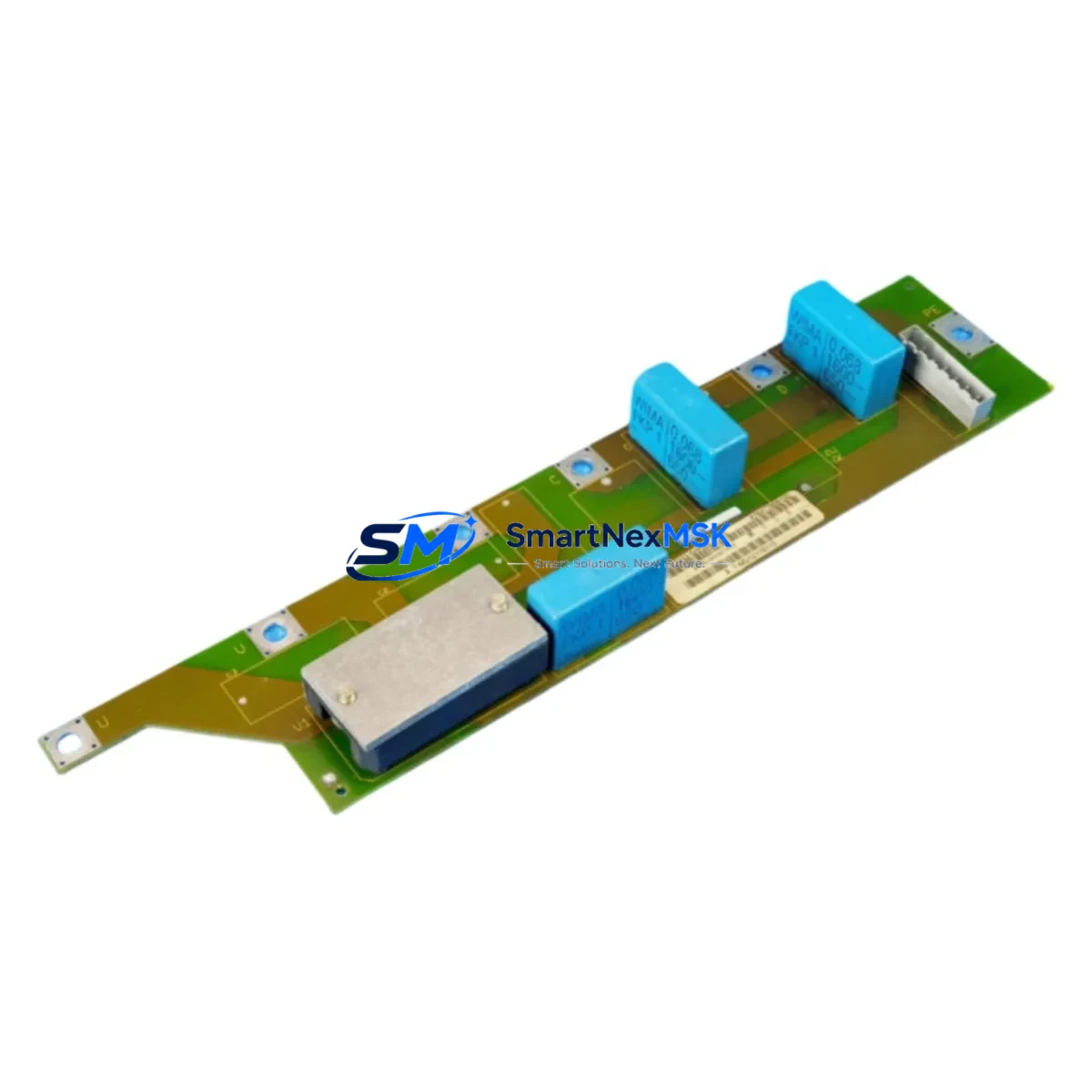
Siemens 6SE7033-5HH84-1HH0 Retrofit-Ready Rectifier for MASTERDRIVES Control Systems
The Siemens 6SE7033-5HH84-1HH0 is a high-capacity rectifier power supply module engineered for the SIMOVERT MASTERDRIVES series. As legacy drive systems approach end-of-life and OEM support windows close, this module serves as a verified retrofit solution for facilities seeking to extend operational continuity without full system replacement. Whether you are upgrading an aging control cabinet, recovering from an unplanned drive failure, or executing a planned modernization of a production line, the 6SE7033-5HH84-1HH0 provides a structurally compatible, electrically matched replacement path for the original MASTERDRIVES rectifier stage.
Upgrade Compatibility Table
| Parameter | Details |
|---|---|
| Compatible Series | SIMOVERT MASTERDRIVES MC / VC / FC |
| Mounting Interface | Standard MASTERDRIVES chassis rail, direct backplane insertion |
| Input Voltage | 3AC 380–480 V, ±10% |
| Output DC Bus | Compatible with MASTERDRIVES DC link architecture |
| Communication Compatibility | PROFIBUS-DP via CBP2 communication board; USS protocol supported |
| Replacement Recommendation | Direct drop-in for 6SE7033-5HH84-1HH0; verify firmware revision on CU board |
| Commissioning Notes | Re-parameterize P060 group after installation; confirm DC bus pre-charge sequence |
| Warranty | 12 Months — covers manufacturing defects and functional failure under normal operating conditions |
Retrofit Planning for Existing Automation Systems
Successful integration of the 6SE7033-5HH84-1HH0 into an existing MASTERDRIVES installation requires systematic pre-commissioning verification across several subsystems. Begin by auditing the incoming power supply capacity: confirm that the upstream transformer and circuit breaker ratings support the rectifier’s full load draw, particularly in multi-drive cabinet configurations where shared DC bus topologies are common.
Terminal wiring must be mapped against the original installation drawings. The L1/L2/L3 AC input terminals and the DC+ / DC- bus connections should be verified for correct torque values and conductor cross-section compliance. If the original installation used a 6SE7090-0XX84-0AB0 line filter or a 6SE7033-series line reactor, confirm that these upstream components remain serviceable and correctly rated for the replacement module’s input current profile.
The MASTERDRIVES control unit — typically a CU3 or CU-VC board — communicates with the rectifier via the internal backplane interface. Before powering up, verify that the CU board firmware is compatible with the replacement module’s hardware revision. In systems where a CBP2 PROFIBUS communication board is installed, re-check the PROFIBUS node address and baud rate settings, as these are stored in the CU board’s non-volatile memory and should survive module replacement without reprogramming.
For cabinets that also house an inverter module such as the 6SE7032-series or a 6SE7036-series unit, confirm that the shared DC bus voltage remains within the inverter’s input tolerance window during the rectifier’s pre-charge phase. The pre-charge relay sequence — managed by the 6SE7090-0XX84-2DA0 pre-charging unit in larger configurations — must complete successfully before the main contactor closes. Failure to verify this sequence is a common source of nuisance trips during post-retrofit commissioning.
If the system includes a Siemens OP1S operator panel or an external HMI connected via the USS interface on the BOP link, re-validate the HMI parameter mapping after module replacement. Drive parameter sets exported via DriveMonitor or STARTER software should be re-uploaded to the CU board and verified against the original P-list to ensure that ramp times, current limits, and speed reference scaling remain intact. Pay particular attention to parameters in the P300–P400 range governing motor data and flux control, as these directly affect post-retrofit motor performance.
In I/O-intensive applications, check that any 6SE7090-series technology boards or 6SE7031-series expansion I/O modules mounted on the same chassis are correctly addressed and that their terminal assignments have not shifted due to rack reconfiguration. Where a SIMATIC S7-300 or S7-400 PLC is the upstream controller, verify that the drive’s PROFIBUS GSD file version matches the configuration loaded in the PLC’s hardware catalog in STEP 7 or TIA Portal.
Downtime Control During System Migration
Minimizing production downtime during a MASTERDRIVES rectifier replacement requires a structured pre-outage preparation protocol. Before the scheduled maintenance window, export the complete drive parameter set using DriveMonitor or STARTER and store a backup on an external device. Photograph or document all terminal wiring, cable routing, and shield grounding points inside the control cabinet.
During the outage, follow the MASTERDRIVES de-energization sequence: disable the drive enable signal from the PLC, allow the DC bus to discharge fully (verify with a calibrated voltmeter — do not rely solely on the discharge indicator LED), then isolate the main supply. Module extraction and insertion should follow the mechanical guide rail alignment procedure described in the MASTERDRIVES hardware installation manual to avoid backplane connector damage.
After installing the 6SE7033-5HH84-1HH0, restore power in stages: apply control voltage first, confirm CU board boot and parameter recognition, then close the main contactor and monitor the pre-charge sequence. Re-upload the saved parameter set, perform a no-load test run, and verify speed reference tracking and current feedback before returning the drive to production. A structured commissioning checklist reduces the risk of overlooked settings and supports a controlled, documented return to service — typically achievable within a single planned maintenance shift.
Retrofit Support FAQ
Q: Is the 6SE7033-5HH84-1HH0 a direct replacement for the original module without parameter changes?
A: In most cases, yes — the module is electrically and mechanically compatible with the original MASTERDRIVES chassis. However, it is best practice to re-verify the P060 commissioning parameter group and confirm DC bus pre-charge behavior after installation, particularly if the CU board firmware has been updated since the original commissioning.
Q: What wiring checks are required before powering up the replacement module?
A: Verify AC input terminal torque, DC bus connection polarity, PE grounding continuity, and upstream line filter or reactor ratings. Confirm that all control wiring to the CU board terminal strip is intact and that no shield grounds have been disturbed during module removal.
Q: How is compatibility with the existing PROFIBUS network confirmed?
A: The PROFIBUS node address and baud rate are stored in the CU board, not the rectifier module, so network configuration is preserved across module replacement. After installation, perform a PROFIBUS diagnostic scan from the PLC to confirm that the drive responds correctly at its assigned address before enabling the drive from the control program.
Q: What does the 12-month warranty cover?
A: The 12-month warranty covers manufacturing defects and functional failure under normal industrial operating conditions. Each unit undergoes pre-shipment functional testing. Warranty claims are supported by our technical team at [email protected] with documented failure analysis and replacement dispatch.
© 2026 SMARTNEXMSK. All rights reserved.
Original Source: https://smartnexmsk.com
Contact: [email protected] | +86 18259474341



