
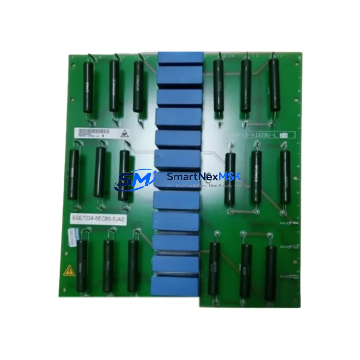
Siemens 6SE7034-6EC85-0JA0 Maintenance-Ready Spare for MASTERDRIVES Automation
The Siemens 6SE7034-6EC85-0JA0 is a high-power AC inverter drive module from the SIMOVERT MASTERDRIVES series, engineered for demanding industrial automation environments. As a maintenance-ready spare, this unit is sourced as an original Siemens component, pre-tested before shipment, and backed by a 12-month warranty — making it a reliable choice for maintenance engineers managing critical drive systems in continuous production facilities.
Unplanned drive failures in MASTERDRIVES-based systems can result in extended production downtime, especially in legacy installations where replacement lead times from OEM channels may stretch weeks. Stocking the 6SE7034-6EC85-0JA0 as a verified spare eliminates this risk, enabling same-shift restoration of drive functionality and protecting production continuity. This module is widely deployed in steel processing, paper mills, chemical plants, crane systems, and heavy-duty conveyor applications where high-torque variable-speed control is essential.
Spare Maintenance Table
| Part Number | 6SE7034-6EC85-0JA0 |
| Brand | Siemens |
| Series | SIMOVERT MASTERDRIVES |
| Product Type | AC Inverter Drive Module |
| Output Power Class | High-power (inferred: ~160–200 kW range, 6SE7034 series) |
| Supply Voltage | 3-phase AC, 380–480 V (±10%) |
| Output Frequency | 0–300 Hz (vector/V/f control) |
| Cooling Method | Forced air / liquid-cooled chassis (0JA0 suffix) |
| Control Mode | Sensorless vector, closed-loop vector, V/f |
| Communication Interface | PROFIBUS DP (via CBP2 option board), USS protocol |
| Compatibility | SIMOVERT MASTERDRIVES MC/VC chassis units; compatible with existing 6SE70xx series installations |
| Origin | Germany |
| Condition | Original, new or refurbished-to-spec; tested before shipment |
| Installation | Chassis/cabinet mount; DIN rail accessories available |
| Operating Temperature | 0°C to +40°C (derating above 40°C) |
| Protection Class | IP20 (cabinet installation required) |
| Warranty | 12 Months |
| Shipping | Tested before dispatch; secure industrial packaging |
Maintenance Planning for Continuous Operation
When replacing the 6SE7034-6EC85-0JA0 in a MASTERDRIVES installation, a thorough site inspection of the surrounding electrical system is essential to prevent repeat failures and ensure long-term drive reliability. Maintenance engineers should treat this replacement as an opportunity to audit the full drive cabinet and associated control loop.
Begin with the DC bus capacitor bank and pre-charge resistor assembly — these components age in parallel with the inverter module and are common root causes of recurring drive faults. Inspect the MASTERDRIVES power supply module (e.g., 6SE7031 rectifier/regenerative unit) for signs of thermal stress or capacitor bulging. Verify that the DC link voltage is within specification before energizing the replacement module.
Check all power cabling and bus bar connections for torque compliance and insulation integrity. Loose connections at the DC bus or motor output terminals are a frequent cause of IGBT failure in high-power drives. Inspect the motor output filter or dV/dt filter if installed, as a degraded filter can stress the new module’s output stage.
On the control side, verify the PROFIBUS CBP2 communication board and its fiber-optic or copper interface to the PLC or DCS. A faulty CBP2 can cause intermittent communication faults that are misdiagnosed as drive hardware failures. Review the CU (Control Unit) firmware version — particularly the 6SE7090-0XX84-0FA0 or equivalent — to confirm compatibility with the replacement inverter module.
Inspect I/O terminal strips and signal wiring at the CU board: analog speed reference inputs (0–10 V / 4–20 mA), digital enable signals, and fault relay outputs. Corroded or loose terminals at these points can cause erratic drive behavior after replacement. If the installation includes a Siemens OP1S operator panel or external HMI, confirm that parameter sets are backed up before swapping the module, as some configurations store drive parameters locally.
For systems with encoder feedback (HTL/TTL pulse encoder) connected via the SBP or SBM option board, verify encoder cable shielding and connector integrity. Signal noise on the encoder line can cause speed regulation instability in closed-loop vector mode. Additionally, inspect the cabinet cooling fans and air filters — blocked airflow is the leading cause of thermal shutdown in high-power MASTERDRIVES chassis units.
Where the drive interfaces with a Siemens S7-300 or S7-400 PLC via PROFIBUS, confirm that the GSD file and hardware configuration in STEP 7 or TIA Portal match the replacement module’s firmware. Mismatched configurations can prevent the drive from entering the “ready” state after replacement.
Site Replacement Workflow
Step 1 — Isolation & Lockout: De-energize the drive cabinet and apply LOTO (Lockout/Tagout) per site safety procedures. Allow a minimum of 5 minutes for DC bus capacitors to discharge before opening the cabinet. Verify DC bus voltage with a calibrated meter before touching internal components.
Step 2 — Parameter Backup: If the existing drive is still partially functional, upload the full parameter set using STARTER software or the OP1S panel. Save the parameter file to a secure location. This eliminates re-commissioning time after module swap.
Step 3 — Module Removal: Disconnect DC bus bars, motor output cables, and control wiring in sequence. Label all connections before removal. Note the torque values for bus bar bolts (typically 10–25 Nm depending on bus size) for reinstallation.
Step 4 — Replacement Installation: Install the 6SE7034-6EC85-0JA0 into the chassis frame. Reconnect DC bus, motor output, and control wiring. Torque all power connections to specification. Verify that the cooling fan connector is seated correctly.
Step 5 — Parameter Restore & Commissioning: Download the saved parameter set to the replacement module. Perform a no-load test run at low speed before connecting the motor load. Verify speed reference, fault relay, and PROFIBUS communication status from the PLC.
Step 6 — Load Test & Handover: Run the drive under partial load, monitoring output current, DC bus voltage, and heatsink temperature. Confirm stable operation across the full speed range before returning the system to production. Document the replacement in the site maintenance log.
This structured workflow minimizes downtime, reduces the risk of repeat failures, and ensures the replacement module operates within its design parameters from the first power-on.
Spare Parts Support FAQ
Q1: Is the 6SE7034-6EC85-0JA0 a direct drop-in replacement for other 6SE7034 variants?
The 6SE7034-6EC85-0JA0 shares the same chassis form factor and control interface as other 6SE7034-series modules, but the -0JA0 suffix denotes a specific cooling and hardware configuration. Always verify the full part number against your existing installation before ordering. Our technical team can assist with compatibility confirmation based on your cabinet documentation or nameplate data.
Q2: What is included in the 12-month warranty and pre-shipment testing?
Every unit undergoes functional testing prior to dispatch, including DC bus charge/discharge verification, IGBT gate drive integrity check, and control board communication test. The 12-month warranty covers manufacturing defects and functional failures under normal operating conditions. It does not cover damage resulting from incorrect installation, overvoltage events, or environmental contamination beyond the module’s IP rating.
Q3: How should I manage spare inventory for MASTERDRIVES systems in aging facilities?
For facilities with multiple MASTERDRIVES installations, we recommend maintaining at least one 6SE7034-series spare per power class tier in your on-site spare parts store. Given that Siemens has transitioned MASTERDRIVES to limited availability status, sourcing replacement modules through specialist distributors is increasingly important. Pairing the inverter spare with a backup CBP2 communication board and a set of DC bus fuses provides comprehensive coverage for the most common failure modes.
Q4: Can this module be used to replace a failed unit in a regenerative (AFE) MASTERDRIVES system?
The 6SE7034-6EC85-0JA0 is an inverter (motoring) module. In a regenerative MASTERDRIVES system, the rectifier/AFE unit is a separate module (typically a 6SE703x-xExx5-0AA0 series). Replacing the inverter module in a regenerative system does not affect the AFE unit’s functionality, provided the DC bus interface and control wiring are correctly restored. Confirm the system topology with your site electrical drawings before proceeding.
© 2026 SMARTNEXMSK. All rights reserved.
Original Source: https://smartnexmsk.com
Contact: [email protected] | +86 18259474341



