
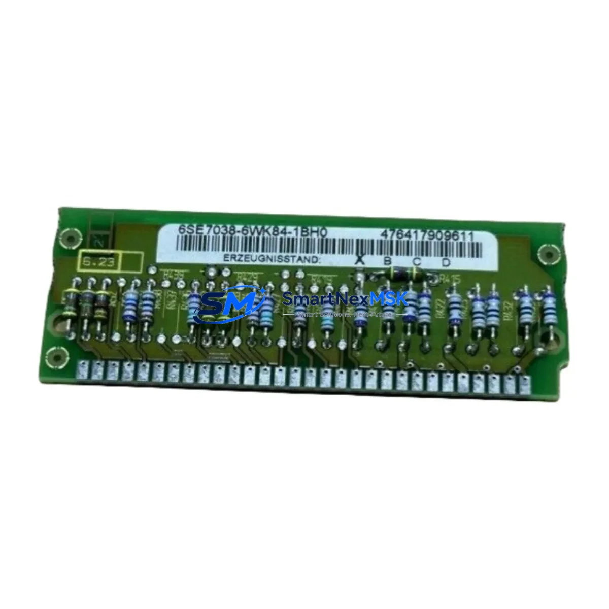
Siemens 6SE7035-7WK84-1BH0 Retrofit-Ready AC Drive for MASTERDRIVES VC Control Systems
The Siemens 6SE7035-7WK84-1BH0 is a 200 kW SIMOVERT MASTERDRIVES Vector Control (VC) AC variable frequency drive engineered for demanding industrial environments. As legacy MASTERDRIVES VC units reach end-of-service life, this unit serves as the authoritative retrofit and replacement solution for production lines, compressor stations, pump systems, and heavy-duty conveyor applications where unplanned downtime carries significant operational cost. Whether you are executing a planned control-cabinet upgrade or responding to an emergency spare-parts shortage, the 6SE7035-7WK84-1BH0 provides a verified, drop-in-compatible path forward with full 12-month warranty coverage and pre-shipment functional testing.
Upgrade Compatibility Table
| Parameter | Detail |
|---|---|
| SKU / Part Number | 6SE7035-7WK84-1BH0 |
| Series | SIMOVERT MASTERDRIVES VC |
| Power Rating | 200 kW (at 380–480 V AC, 3-phase) |
| Enclosure / Form Factor | Chassis unit, booksize mounting |
| Backplane Interface | MASTERDRIVES VC rack-compatible slot |
| Communication Compatibility | PROFIBUS-DP (CBP2 board), USS protocol |
| Replacement Scope | Direct replacement for discontinued 6SE70 series VC units of equivalent power class |
| Terminal Wiring | Compatible with existing X1/X2 power terminals and CU control board connectors |
| Commissioning Tool | STARTER software / DriveMonitor via PC adapter (e.g., 6SE7090-0XX84-0FF5) |
| Pre-Shipment Test | Full functional test performed before dispatch |
| Warranty | 12 months from date of shipment |
Retrofit Planning for Existing Automation Systems
A successful retrofit of the 6SE7035-7WK84-1BH0 into an existing MASTERDRIVES VC installation begins well before the unit arrives on site. Engineers should first audit the existing control cabinet for available DC bus capacity and verify that the incoming supply voltage and frequency match the drive’s rated input parameters. The existing Siemens MASTERDRIVES VC rack and backplane must be inspected for mechanical integrity, as the 6SE7035-7WK84-1BH0 mounts directly into the same chassis slot used by the predecessor unit.
Terminal wiring is a critical checkpoint. The X1 and X2 power terminals on the 6SE7035-7WK84-1BH0 follow the same physical layout as earlier MASTERDRIVES VC chassis units, but engineers must confirm cable cross-sections are rated for the 200 kW load and that PE (protective earth) bonding meets local installation standards. The CU (Control Unit) board — typically a CU3 or equivalent — connects via the internal bus connector and must be verified for firmware compatibility before the new drive is powered up.
Communication integration is the next layer. Most legacy MASTERDRIVES VC installations rely on PROFIBUS-DP for PLC-to-drive communication, using a CBP2 communication board seated in the option slot. When retrofitting the 6SE7035-7WK84-1BH0, the existing CBP2 board can typically be transferred directly, preserving the PROFIBUS node address and GSD file configuration already loaded in the Siemens S7-300 or S7-400 PLC project. If the site is migrating from PROFIBUS to PROFINET as part of a broader control-system upgrade, a CBE20 communication board and corresponding PLC hardware changes — such as adding a Siemens CP 343-1 or CP 443-1 Ethernet module — will be required.
I/O expansion considerations are equally important. Many MASTERDRIVES VC applications use the TB (Terminal Board) and SBx (Sensor Board) option cards for analog speed references, digital enable signals, and encoder feedback. The 6SE7035-7WK84-1BH0 supports the same option board ecosystem, so existing TB30 terminal boards and SB encoder interface cards can be reused without rewiring. However, if the retrofit is combined with an I/O architecture upgrade — for example, migrating discrete I/O to a Siemens ET 200SP distributed I/O station connected via PROFINET — the PLC program and HMI tag database will need corresponding updates.
HMI screen adaptation is often underestimated in retrofit projects. Siemens WinCC or WinCC flexible panels that display drive status, speed setpoints, and fault codes typically read data from the PLC’s drive function blocks. After replacing the drive unit, engineers should verify that all drive parameter mappings in the PLC program (using standard Siemens FC or FB drive blocks) remain valid and that HMI faceplates reflect the correct fault code descriptions for the 6SE7035-7WK84-1BH0 firmware version.
Finally, the programming cable and commissioning software must be prepared in advance. STARTER software connected via a PC adapter (such as the 6SE7090-0XX84-0FF5 serial adapter or a USS/PROFIBUS interface) allows engineers to upload the parameter set from the outgoing drive before removal and download it to the replacement unit. This parameter backup — covering ramp times, current limits, motor data, and control mode settings — is the single most effective measure for reducing commissioning time and protecting the integrity of the original control logic.
Downtime Control During System Migration
Minimizing production downtime during a MASTERDRIVES VC replacement requires a structured pre-outage preparation protocol. Before the scheduled maintenance window, the site engineer should use STARTER or DriveMonitor to export a complete parameter backup (P0010 upload) from the existing drive. This file, stored on a laptop or USB drive, contains all motor data, ramp profiles, PID settings, and communication parameters needed to restore the replacement unit to an identical operating state.
During the outage, the sequence should follow a defined order: isolate and lock out the incoming supply, discharge the DC bus capacitors (allow a minimum of five minutes after isolation), remove the existing drive chassis, install the 6SE7035-7WK84-1BH0, reconnect power terminals and control wiring, reseat the CBP2 communication board and any TB or SB option cards, and restore the parameter set via STARTER before applying power. This structured approach typically reduces the active replacement window to under four hours for a prepared team, compared to eight or more hours when working without a parameter backup or pre-tested replacement unit.
To protect original program logic, the PLC should remain in STOP mode throughout the drive replacement. The Siemens S7 PLC’s drive function blocks will generate a communication fault during the outage window, which is expected behavior. Once the replacement drive is powered and the PROFIBUS link is re-established, the PLC can be returned to RUN mode and the drive enabled through the normal startup sequence. Field verification should include a no-load run at low speed, followed by a loaded ramp-up to confirm current limits, speed accuracy, and fault-free operation before returning the line to production.
Retrofit Support FAQ
Q1: Is the 6SE7035-7WK84-1BH0 a direct drop-in replacement for my existing MASTERDRIVES VC unit?
A: Yes, for units of equivalent power class within the SIMOVERT MASTERDRIVES VC chassis family. The mechanical mounting, backplane connector, and terminal layout are compatible. You should verify the firmware version of your existing CU board and confirm that the motor data parameters are correctly transferred via STARTER before commissioning.
Q2: Can I reuse my existing PROFIBUS-DP wiring and CBP2 communication board?
A: In most cases, yes. The CBP2 board can be transferred from the outgoing unit to the 6SE7035-7WK84-1BH0 without changes to the PROFIBUS node address or GSD configuration. Confirm that the board’s firmware is compatible with the replacement drive’s CU firmware version before powering up.
Q3: What pre-shipment testing is performed on the 6SE7035-7WK84-1BH0?
A: Each unit undergoes a full functional test prior to dispatch, including power-on verification, parameter initialization, and communication interface checks. A test report is available upon request. The unit ships with a 12-month warranty from the date of shipment.
Q4: What should I do if my original drive’s parameter backup is unavailable?
A: If no parameter backup exists, our technical team can assist with reconstructing a baseline parameter set based on the motor nameplate data, application type, and known MASTERDRIVES VC default settings. We recommend performing a motor identification run (P1910) during commissioning to optimize current control and ensure accurate torque response before returning the line to production.
© 2026 SMARTNEXMSK. All rights reserved.
Original Source: https://smartnexmsk.com
Contact: [email protected] | +86 18259474341



