
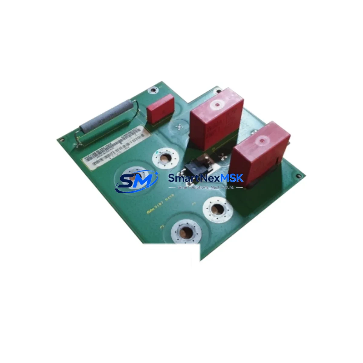
Siemens 6SE7038-6EK84-1GG0 Retrofit-Ready Output Module for MASTERDRIVES Control Systems
The Siemens 6SE7038-6EK84-1GG0 is a high-power AC drive output module designed for the MASTERDRIVES MC (Motion Control) and VC (Vector Control) platform. As legacy MASTERDRIVES installations approach end-of-service milestones, this module remains one of the most sought-after retrofit and replacement components for engineers tasked with modernizing existing drive cabinets without full system replacement. Whether you are restoring a failed drive train, upgrading a parallel inverter configuration, or migrating from an older SIMOVERT MASTERDRIVES 6SE70 series unit, the 6SE7038-6EK84-1GG0 provides a verified, wiring-compatible upgrade path that minimizes engineering rework and production downtime.
This output module is rated for high-current inverter duty and is engineered to integrate directly into existing MASTERDRIVES compact-plus or chassis-format enclosures. The module interfaces with the standard MASTERDRIVES CU (Control Unit) via the internal fiber-optic SIMOLINK or CBP2 PROFIBUS communication board, preserving existing drive parameterization and motor control logic stored in the CU. Engineers replacing a failed output module in a running system can retain the existing CU, the 6SE7090-0XX84-0KA0 interface board, and the associated 6SE7038-6EK84-0AA0 base drive assembly, significantly reducing the scope of the retrofit.
Before installation, the following verification steps are critical to a successful retrofit: confirm DC bus voltage compatibility and verify that the existing 6SE7038-6EK84-1HF0 rectifier or active front-end unit can supply adequate DC link current for the replacement module’s rated output. Check the terminal block layout against the existing wiring harness — the 6SE7038-6EK84-1GG0 uses the standard MASTERDRIVES U1/V1/W1 AC input and U2/V2/W2 motor output terminal arrangement, which is consistent across the 6SE703x chassis series. Verify that the backplane slot assignment and module address configuration in the CU parameter set (P060 and P070 groups) match the replacement unit’s hardware revision.
For sites running SIMATIC S7-300 or S7-400 PLCs with PROFIBUS-DP drive integration, the CBP2 communication board installed in the existing drive must be re-addressed after module swap to ensure the DP slave address is correctly recognized by the PLC program. If the site uses a 6GK7 343-1EX30-0XE0 CP343-1 Ethernet module or a 6ES7 315-2EH14-0AB0 CPU for coordinated motion, the drive telegram type (typically PPO Type 3 or 4) should be confirmed in the STEP 7 hardware configuration before commissioning. HMI screens built on WinCC or SIMATIC OP/TP panels referencing drive status words will continue to function without modification provided the telegram structure is preserved.
Power supply integrity is a common failure point during retrofit. Confirm that the 24 VDC control supply — typically sourced from a 6EP1 334-2AA01 SITOP PSU300S or equivalent — is within tolerance before energizing the replacement module. The 6SE7038-6EK84-1GG0 draws approximately 2.5 A from the 24 VDC rail for control electronics; insufficient supply capacity is a frequent cause of post-replacement fault codes. Additionally, inspect the existing motor cable for insulation integrity using a 1000 V megger test before reconnecting to the new output stage, as degraded motor insulation can cause immediate IGBT failure in the replacement module.
For multi-drive installations using a common DC bus topology — a configuration frequently found in paper mills, steel processing lines, and material handling systems — the 6SE7038-6EK84-1GG0 must be synchronized with the active rectifier unit during commissioning. Use the MASTERDRIVES MC commissioning tool (DriveMonitor or STARTER software) to perform the automatic motor identification routine (P115 = 1) and re-optimize the speed controller parameters. If the original drive was running a customized technology function (T400 or T500 technology board), verify that the technology software version is compatible with the replacement module’s firmware revision before loading the existing parameter set.
All units supplied by SMARTNEXMSK are sourced from verified industrial surplus and authorized distribution channels. Each 6SE7038-6EK84-1GG0 module undergoes functional inspection and load testing prior to shipment. Units are shipped with original or equivalent packaging, and full documentation including the hardware installation manual is available upon request. Stock is maintained in Xiamen for prompt dispatch to domestic and international customers. A 12-month warranty is provided on all units, covering manufacturing defects and functional failures under normal operating conditions.
Upgrade Compatibility Table
| Parameter | Details |
|---|---|
| SKU / Part Number | 6SE7038-6EK84-1GG0 |
| Platform | Siemens MASTERDRIVES MC / VC (6SE70 Series) |
| Module Type | AC Drive Output Module (Inverter Section) |
| DC Bus Interface | Standard MASTERDRIVES chassis DC link bus bar |
| Control Interface | Compatible with 6SE70 CU (Control Unit) via fiber-optic SIMOLINK |
| Communication Compatibility | PROFIBUS-DP via CBP2 board; SIMOLINK fiber ring |
| Terminal Wiring | U1/V1/W1 (AC input) / U2/V2/W2 (motor output) — standard 6SE703x layout |
| Backplane / Rack | MASTERDRIVES chassis format; slot-compatible with 6SE7038-6EK84-0AA0 base |
| Replacement For | 6SE7038-6EK84-1GF0, 6SE7038-6EK84-1GG0 (prior hardware revisions) |
| Retrofit Recommendation | Retain existing CU, CBP2, and interface board; replace output module only |
| Commissioning Tool | DriveMonitor / STARTER (Siemens); P115=1 motor ID routine required |
| Warranty | 12 Months — covers manufacturing defects and functional failures |
Retrofit Planning for Existing Automation Systems
A successful retrofit of the 6SE7038-6EK84-1GG0 into an existing MASTERDRIVES installation requires a structured approach to component verification and sequenced replacement. In a typical drive cabinet, the output module works in conjunction with the 6SE7038-6EK84-0AA0 base drive unit, the 6SE7090-0XX84-0KA0 interface board, and the 6SE7031-8EF84-1JC1 or equivalent CU (Control Unit). The 24 VDC control power rail, typically fed by a 6EP1 334-2AA01 SITOP power supply, must be verified for load capacity before energizing the new module.
I/O expansion cards installed in the CU — such as the 6SE7090-0XX84-0FF5 SCI1 serial interface board or the 6SE7090-0XX84-0AB0 ADB analog/digital board — do not require replacement during an output module swap and will retain their parameterization. Similarly, the 6SN1118-0DM23-0AA1 or equivalent encoder evaluation board, if present for closed-loop speed feedback, remains fully compatible. For sites using a SIMATIC HMI panel such as the 6AV6 643-0CD01-1AX1 TP277 or a WinCC-based SCADA system, drive status visualization will be unaffected provided the PROFIBUS address and telegram type are preserved during commissioning.
In common DC bus multi-drive systems, the 6SE7036-0EK85-0AA0 active rectifier unit or the 6SE7031-2EF85-0AA0 basic rectifier must be confirmed as operational before the replacement output module is energized. The DC link voltage should be measured at the bus bar connection points of the new module prior to closing the main contactor. Programming cables such as the 6ES7 972-0CB20-0XA0 PC adapter for PROFIBUS or the USB-MPI adapter are required for parameter upload/download during the commissioning phase.
Downtime Control During System Migration
Minimizing production downtime during a MASTERDRIVES output module replacement requires advance preparation and a disciplined commissioning sequence. Before the maintenance window begins, upload the complete parameter set from the existing CU using DriveMonitor or STARTER software and save it to a secure backup file. Document all fault history codes, motor nameplate data, and any custom technology function parameters. Photograph the existing terminal wiring before disconnection to provide a reference for reconnection.
During the replacement window, the mechanical swap of the 6SE7038-6EK84-1GG0 output module can typically be completed within 30–60 minutes for an experienced technician familiar with the MASTERDRIVES chassis format. The critical path items are DC bus discharge verification (minimum 5-minute wait after power-off before touching bus bar connections), torque-correct terminal reconnection, and fiber-optic cable reseating. After mechanical installation, restore the parameter backup to the CU, verify the motor identification routine completes without fault, and perform a no-load test run before reconnecting the mechanical load. This sequence protects the original program logic, preserves HMI screen functionality, and maintains control continuity across the drive network.
Retrofit Support FAQ
Q: Is the 6SE7038-6EK84-1GG0 a direct drop-in replacement for earlier hardware revisions of the same part number?
A: Yes. The 6SE7038-6EK84-1GG0 is mechanically and electrically compatible with earlier hardware revisions within the 6SE7038-6EK84 family. Terminal wiring, backplane interface, and CU communication connections are identical. A motor identification routine (P115=1) is recommended after installation to optimize controller parameters for the specific motor.
Q: Can I retain my existing PROFIBUS configuration and HMI screens after replacing the output module?
A: Yes, provided the CBP2 PROFIBUS board is transferred to the replacement module or retained in the existing CU, and the DP slave address is confirmed unchanged. HMI screens referencing drive status words will continue to function without modification as long as the telegram type (PPO Type 3 or 4) is preserved in the PLC hardware configuration.
Q: What pre-shipment testing is performed on each unit?
A: Each 6SE7038-6EK84-1GG0 unit supplied by SMARTNEXMSK undergoes functional inspection and load testing prior to dispatch. Units are verified for IGBT gate drive integrity, DC bus capacitor condition, and control board communication. A 12-month warranty covering manufacturing defects and functional failures is included with every unit.
Q: What is the lead time and are units available from stock?
A: Units are maintained in stock at our Xiamen warehouse for prompt domestic and international dispatch. Standard lead time for in-stock units is 3–5 business days for domestic delivery. Contact [email protected] or call +86 18259474341 to confirm current availability before placing an order.
© 2026 SMARTNEXMSK. All rights reserved.
Original Source: https://smartnexmsk.com
Contact: [email protected] | +86 18259474341



