
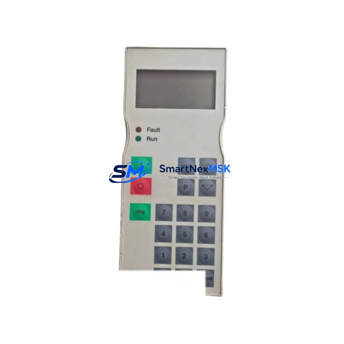
Siemens 6SE7090-0XX84-2FK0 Retrofit-Ready Power Supply for SIMOVERT MASTERDRIVES Control Systems
The Siemens 6SE7090-0XX84-2FK0 is a dedicated power supply module engineered for the SIMOVERT MASTERDRIVES series — one of Siemens’ most widely deployed AC drive platforms in industrial automation. As legacy MASTERDRIVES installations approach end-of-life and original spare parts become increasingly scarce, the 6SE7090-0XX84-2FK0 remains a critical component for engineers tasked with sustaining production continuity, executing planned retrofits, or recovering from unplanned drive failures.
This module provides the regulated DC bus power required to sustain the control electronics within MASTERDRIVES compact and chassis-format units. It is compatible with a broad range of MASTERDRIVES variants including Motion Control (MC), Vector Control (VC), and standard FC configurations. When sourcing this module for a retrofit or emergency replacement, engineers must verify the input voltage range, DC output rating, and the physical form factor against the existing drive chassis — particularly when the original unit has been in service for more than a decade and documentation may be incomplete.
Upgrade Compatibility Table
| Parameter | Details |
|---|---|
| SKU / Part Number | 6SE7090-0XX84-2FK0 |
| Series Compatibility | Siemens SIMOVERT MASTERDRIVES (MC, VC, FC variants) |
| Module Function | AC Drive Power Supply Module |
| Installation Format | Chassis-mount, backplane-integrated |
| Interface / Backplane | MASTERDRIVES standard backplane connector |
| Communication Compatibility | Compatible with PROFIBUS-DP, USS protocol environments |
| Replacement Recommendation | Direct drop-in for same-series power supply modules; verify DC bus rating before installation |
| Commissioning Notes | Parameter upload from existing drive recommended prior to swap; use STARTER or DriveMonitor software |
| Country of Origin | Germany |
| Warranty | 12 Months |
Retrofit Planning for Existing Automation Systems
Replacing the 6SE7090-0XX84-2FK0 in an active production environment requires careful pre-planning across multiple system layers. Before the module is swapped, the engineering team should perform a full parameter backup of the existing MASTERDRIVES unit using Siemens STARTER software or the legacy DriveMonitor tool. This ensures that motor data sets, ramp profiles, torque limits, and application-specific control word configurations are preserved and can be reloaded after the replacement module is installed.
On the hardware side, the retrofit process typically involves inspecting the MASTERDRIVES backplane and verifying that the slot assignment and module address settings are consistent with the original configuration. In multi-axis installations, the drive rack may also house a 6SE7090-0XX84-0FA0 Rectifier/Regenerative Unit or a 6SE7031 series Inverter Module — both of which share the same DC bus and must remain operational during the power supply swap to avoid cascading faults across the drive line-up.
Terminal wiring is another critical checkpoint. The 6SE7090-0XX84-2FK0 connects to the main AC input terminals and the internal DC bus distribution. Engineers should confirm that the existing cable cross-sections, terminal torque specifications, and fuse ratings comply with the replacement module’s input requirements. In older installations, it is common to find undersized wiring or corroded terminal blocks that must be addressed before the new module is energized.
For systems that also include a Siemens OP1S operator panel or a third-party HMI connected via the MASTERDRIVES serial interface, the HMI screen layouts and parameter display assignments should be verified post-commissioning to ensure that drive status words and fault codes are correctly mapped. If the plant uses a SIMATIC S7-300 or S7-400 PLC communicating with the drive over PROFIBUS-DP, the GSD file and DP slave address must be confirmed unchanged after the module replacement — any address conflict will prevent the PLC from re-establishing communication with the drive.
In systems where the MASTERDRIVES unit interfaces with a 6SN1145 series SIMODRIVE power module or coordinates with a SINAMICS G120 or S120 drive on the same control network, the retrofit plan should include a communication link verification step to confirm that the replacement does not disrupt the broader drive coordination logic. Additionally, if the installation includes a 6SE7090-0XX84-3DA1 Braking Module or a shared DC bus configuration, the braking resistor circuit and chopper threshold settings must be re-validated after the power supply is replaced.
For I/O-intensive applications, the retrofit may also require re-checking the 6SE7090-0XX84-0AB0 Technology Board or any installed option boards that provide additional analog and digital I/O channels. These boards retain their own parameter sets and should be individually verified during the commissioning phase.
Downtime Control During System Migration
Minimizing production downtime during a MASTERDRIVES power supply replacement begins with preparation, not execution. The most effective approach is to pre-stage the 6SE7090-0XX84-2FK0 replacement module in advance, perform a full parameter export from the existing drive, and schedule the physical swap during a planned maintenance window rather than responding reactively to a drive fault.
Where possible, a cold-swap procedure should be followed: isolate the drive from the AC supply, discharge the DC bus capacitors to safe levels (typically below 50V DC as measured at the DC bus terminals), and then proceed with the module exchange. After installation, reload the saved parameter set before energizing the drive, and perform a no-load test run to confirm that the motor responds correctly to speed and torque commands before reconnecting the mechanical load.
For critical production lines where even a brief interruption is unacceptable, a hot-standby drive strategy — where a pre-configured spare MASTERDRIVES unit is kept ready for immediate substitution — is strongly recommended. This approach, combined with maintaining a stock of key modules such as the 6SE7090-0XX84-2FK0, significantly reduces mean time to recovery (MTTR) and protects against extended production losses caused by obsolete spare part lead times.
All replacement modules supplied by SMARTNEXMSK are tested prior to shipment and covered by a 12-month warranty. Shipment is available from existing stock, with global logistics support to minimize the time between order placement and on-site availability.
Retrofit Support FAQ
Q1: Is the 6SE7090-0XX84-2FK0 a direct replacement for the original Siemens power supply module in my MASTERDRIVES unit?
A: Yes. The 6SE7090-0XX84-2FK0 is designed as a direct form-fit-function replacement for the original power supply module in compatible SIMOVERT MASTERDRIVES chassis. Before installation, verify the DC bus voltage rating and input voltage range against your drive’s nameplate data to confirm compatibility with your specific unit variant.
Q2: Do I need to re-enter drive parameters after replacing the power supply module?
A: In most cases, drive parameters are stored in the Control Board (CU) rather than the power supply module itself. However, it is strongly recommended to perform a full parameter backup using STARTER or DriveMonitor before any hardware change. This protects against data loss in the event of a CU fault during the swap procedure.
Q3: How do I verify that the replacement module is correctly wired and commissioned?
A: After installation, perform a visual inspection of all AC input and DC bus terminal connections, confirm that all module address settings match the original configuration, and execute a no-load test run. Monitor the drive’s fault and alarm registers during the first powered cycle. For PROFIBUS-DP connected systems, confirm that the PLC re-establishes communication with the drive within the expected timeout period.
Q4: What warranty and pre-shipment testing does SMARTNEXMSK provide for this module?
A: All 6SE7090-0XX84-2FK0 units supplied by SMARTNEXMSK are functionally tested prior to dispatch and covered by a 12-month warranty against manufacturing defects and operational failure. Detailed test records are available upon request. For urgent requirements, expedited shipping options are available to minimize on-site waiting time.
© 2026 SMARTNEXMSK. All rights reserved.
Original Source: https://smartnexmsk.com
Contact: [email protected] | +86 18259474341



