
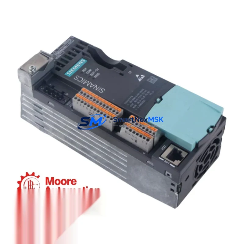
Siemens 6SL3040-1LA01-0AA0 Maintenance-Ready Spare for S120 Automation: Spare Parts Replacement & Downtime Risk Control
The Siemens 6SL3040-1LA01-0AA0 is the CU310-2 PN Control Unit for the SINAMICS S120 single-axis drive system — a mission-critical component in servo and vector drive applications across manufacturing, packaging, printing, and process automation. When this unit fails or reaches end-of-life, the entire drive axis goes offline. Sourcing a verified, tested replacement immediately is the fastest path to restoring production continuity.
This listing provides an original Siemens 6SL3040-1LA01-0AA0 spare, inspected and function-tested prior to shipment, backed by a 12-month warranty. Whether you are executing a planned overhaul, responding to an unplanned fault, or building a strategic spare parts buffer for aging S120 infrastructure, this unit ships ready for direct installation.
Spare Maintenance Table
| Parameter | Specification |
|---|---|
| Part Number (SKU) | 6SL3040-1LA01-0AA0 |
| Description | CU310-2 PN Control Unit, SINAMICS S120 |
| Series | SINAMICS S120 |
| Communication Interface | PROFINET IO (PN), onboard |
| Axis Configuration | Single-axis control |
| Supply Voltage | 24 V DC (via DRIVE-CLiQ or external) |
| Digital Inputs / Outputs | 8 DI / 4 DO (onboard) |
| Encoder Interface | 1× DRIVE-CLiQ, 1× HTL/TTL encoder input |
| Mounting | Booksize format, DIN rail / panel mount |
| Operating Temperature | 0 °C to +55 °C |
| Protection Class | IP20 |
| Country of Origin | Germany |
| Compatibility | SINAMICS S120 Booksize Power Modules (PM340, PM240-2), Motor Modules |
| Firmware | Compatible with STARTER / SINAMICS Startdrive (TIA Portal) |
| Condition | Original, function-tested before shipment |
| Warranty | 12 Months |
Maintenance Planning for Continuous Operation
When a CU310-2 PN (6SL3040-1LA01-0AA0) is flagged for replacement during a scheduled shutdown or emergency fault response, maintenance engineers should treat the event as a trigger for a broader control cabinet inspection. The S120 drive system is deeply integrated — the control unit communicates with the Power Module via DRIVE-CLiQ, and any degradation in the DRIVE-CLiQ communication cable (6SL3060-4AB00-0AA0) or the DRIVE-CLiQ hub module (6SL3162-2BM00-0AA0) can cause recurring faults that are misdiagnosed as CU failures.
Before commissioning the replacement 6SL3040-1LA01-0AA0, verify the 24 V DC auxiliary power supply feeding the control unit — a failing SITOP PSU100S or equivalent 24 V regulated supply is a common root cause of CU310-2 PN brownout faults. Check the 24 V fuse (typically a 2 A miniature fuse on the terminal strip) and inspect the wiring harness for loose ferrules on the X124 connector.
On the I/O side, inspect the digital input wiring at X132 and X142. Corroded or intermittent connections on the enable signal (DI 0) or the safe torque off (STO) circuit can prevent the replacement unit from enabling the drive axis after installation. If the machine uses a safety relay module such as the Siemens 3SK1111 or 3TK2810, verify its output contacts are making cleanly before assuming the new CU is at fault.
For systems using PROFINET communication, confirm the network switch port connected to the CU310-2 PN is operating at 100 Mbit/s full duplex. A misconfigured managed switch or a degraded RJ45 patch cable can cause PROFINET topology errors that appear as drive faults. If the S120 system is integrated with a SIMATIC S7-1500 or S7-300 PLC, verify the GSD file version matches the firmware on the replacement control unit.
Procurement engineers building a spare parts list for S120-based lines should also stock the Compact Flash card (6SL3054-0EJ00-1BA0) pre-loaded with the drive project, as this allows rapid parameter restore without a laptop connection. Keeping one spare Motor Module (e.g., 6SL3120-1TE21-0AA3) and a set of DRIVE-CLiQ cables on the shelf alongside the CU310-2 PN significantly reduces mean time to repair (MTTR) for single-axis servo faults.
Site Replacement Workflow
Step 1 — Isolation: De-energize the drive cabinet. Lock out / tag out per site procedure. Confirm 0 V on the DC bus using a calibrated meter before opening the booksize frame.
Step 2 — Parameter Backup: If the existing CU310-2 PN is still partially functional, use STARTER or TIA Portal Startdrive to upload the current drive project to a PC or Compact Flash card. This eliminates re-commissioning time after the swap.
Step 3 — Hardware Swap: Disconnect the DRIVE-CLiQ cable, the 24 V supply connector (X124), the I/O connector (X132/X142), and the PROFINET cable. Remove the faulty 6SL3040-1LA01-0AA0 from the booksize mounting rail. Install the replacement unit and reconnect all cables in reverse order. Torque terminal screws to specification.
Step 4 — Firmware & Parameter Restore: Insert the Compact Flash card with the saved project, or download the project from the engineering PC. Perform a RAM-to-ROM save after successful parameter transfer. Verify firmware version compatibility with the connected Motor Module and Power Module.
Step 5 — Functional Test: Enable the drive in manual mode. Verify encoder feedback, speed reference tracking, and STO function before returning the axis to automatic production mode. Document the replacement in the maintenance log with the new unit serial number.
This workflow typically achieves axis restoration within 2–4 hours for a prepared maintenance team, compared to 1–3 days when sourcing parts reactively without a spare buffer.
Spare Parts Support FAQ
Q1: Is the 6SL3040-1LA01-0AA0 a direct drop-in replacement for older CU310-2 PN variants?
Yes. The 6SL3040-1LA01-0AA0 is the standard CU310-2 PN with PROFINET interface and is mechanically and electrically compatible with all S120 Booksize Power Modules and Motor Modules. Firmware may need to be updated to match the existing drive project version — this is a standard commissioning step and does not require hardware modification.
Q2: What pre-shipment testing is performed on this spare?
Each unit undergoes power-on functional verification, DRIVE-CLiQ port communication check, and I/O continuity testing before dispatch. A test report is available on request. Units are packed in anti-static ESD packaging with foam protection to prevent transit damage.
Q3: How should this spare be stored if not immediately installed?
Store in a dry environment at 15–35 °C, away from direct sunlight and electromagnetic interference sources. Keep in the original ESD packaging. Inspect annually for any signs of capacitor aging or connector oxidation. Shelf life under proper storage conditions exceeds 5 years.
Q4: What is covered under the 12-month warranty?
The 12-month warranty covers manufacturing defects and functional failures under normal operating conditions. It does not cover damage caused by incorrect installation, overvoltage events, or unauthorized modification. Warranty claims are processed within 5 business days of receiving the returned unit, with replacement or repair at no additional cost.
© 2026 SMARTNEXMSK. All rights reserved.
Original Source: https://smartnexmsk.com
Contact: [email protected] | +86 18259474341



