
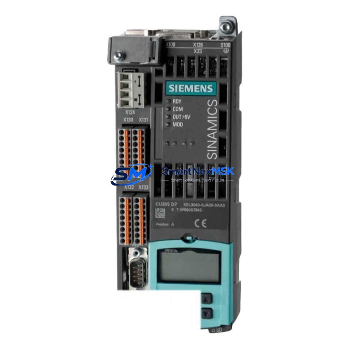
Siemens 6SL3054-0FB00-1BA0 Retrofit-Ready Smart Line Module for SINAMICS S120 Control Systems
The Siemens 6SL3054-0FB00-1BA0 is a Booksize-format Smart Line Module (SLM) designed for the SINAMICS S120 drive platform. As an Active Front End (AFE) power supply unit, it delivers regulated DC bus voltage to connected Motor Modules while enabling energy regeneration back to the supply grid. For facilities operating legacy SINAMICS S120 installations — including older Booksize chassis configurations, first-generation CU320 Control Units, and early-series Motor Modules — this unit represents the most direct, lowest-risk path to restoring or upgrading drive system performance without a full panel redesign.
Whether you are replacing a failed unit on a production line, modernizing a control cabinet that has reached end-of-service life, or migrating from a discontinued predecessor module, the 6SL3054-0FB00-1BA0 is engineered to slot into existing Booksize rack assemblies with minimal rewiring. Its compatibility with the DRIVE-CLiQ communication backbone means that integration with a CU320-2 Control Unit or CU310-2 DP requires only topology re-commissioning in STARTER or TIA Portal — no hardware bus adapters are needed.
Upgrade Compatibility Table
| Parameter | Details |
|---|---|
| SKU / Order Number | 6SL3054-0FB00-1BA0 |
| Series | SINAMICS S120 Booksize |
| Module Type | Smart Line Module (AFE) |
| DC Bus Interface | Booksize DC bus bar (shared rail with Motor Modules) |
| DRIVE-CLiQ Ports | 2 × DRIVE-CLiQ (compatible with CU320, CU320-2, CU310-2) |
| Installation Format | Booksize chassis, DIN rail or panel mount |
| Cooling | Forced air (internal fan); ensure cabinet airflow ≥ rated CFM |
| Communication Compatibility | PROFIBUS DP, PROFINET (via Control Unit); DRIVE-CLiQ native |
| Replacement Fit | Direct drop-in for same-frame SLM variants in S120 Booksize rack |
| Commissioning Tool | STARTER v4.x / TIA Portal V15+ |
| Firmware Requirement | Align firmware version with existing CU320/CU320-2 firmware baseline |
| Warranty | 12 Months — covers manufacturing defects, functional failure under rated load |
Retrofit Planning for Existing Automation Systems
A successful retrofit begins well before the module arrives on site. Engineers replacing a failed or end-of-life Smart Line Module in an S120 Booksize cabinet must audit the full power chain. Start by verifying that the existing Line Filter (e.g., 6SL3000-0BE23-6AA0 or equivalent) and Line Reactor are rated for the SLM’s input current. Undersized line-side components are a common cause of nuisance trips after module replacement.
Next, inspect the Booksize Power Module rack and DC bus bar assembly. Confirm that bus bar connectors are undamaged and that the mechanical mounting positions align with the 6SL3054-0FB00-1BA0 footprint. If the rack also houses Single Motor Modules (e.g., 6SL3120-1TE21-0AA3) or Double Motor Modules, verify that the combined DC bus load does not exceed the SLM’s rated output power.
DRIVE-CLiQ topology is the next critical checkpoint. The 6SL3054-0FB00-1BA0 connects to the CU320-2 Control Unit via DRIVE-CLiQ port X100 or X101. If the existing installation uses an older CU320 (not CU320-2), confirm firmware compatibility before swapping the SLM. In mixed topologies where a Sensor Module Cabinet-Mounted (SMC30) or Terminal Module (TM31) is daisy-chained on the same DRIVE-CLiQ string, re-validate the topology scan in STARTER after installation to ensure all nodes are recognized correctly.
For cabinets that also integrate a Basic Operator Panel (BOP20) or a SIMATIC HMI TP700 Comfort panel, update the drive parameter dataset (p0015 macro, p0700 command source, p1000 setpoint source) after replacement. HMI screen tags linked to drive fault codes and status words should be re-tested against the new module’s diagnostic register map to avoid false alarm displays during initial run-up.
If the system communicates over PROFIBUS DP using a CBE20 Communication Board or the Control Unit’s onboard DP interface, re-check the GSD file version and slave address assignment. PROFINET installations should verify the device name assignment and IP address configuration in TIA Portal’s device view before going live.
Terminal wiring on the SLM’s X1 (mains connection) and X2 (PE/ground) terminals must be re-torqued to specification. Cross-reference the existing wiring diagram against the 6SL3054-0FB00-1BA0 terminal layout — particularly if the previous module was from an earlier hardware revision with a different terminal pitch. Label all conductors before disconnection to eliminate re-wiring errors during installation.
Downtime Control During System Migration
Minimizing production downtime during an SLM replacement requires a structured pre-outage preparation protocol. Before the scheduled maintenance window, use STARTER or TIA Portal to export the complete drive project — including all axis parameter sets, safety parameters (if STO/SS1 is active), and the DRIVE-CLiQ topology backup. Store this backup on a SIMATIC Memory Card or a local engineering workstation so that re-commissioning can begin immediately after the new module is seated.
During the outage, follow a strict sequence: isolate mains supply → discharge DC bus (verify with a calibrated voltmeter; allow minimum 5 minutes after isolation) → disconnect DRIVE-CLiQ cables → remove DC bus bar connectors → extract the failed module → install 6SL3054-0FB00-1BA0 → reconnect in reverse order. Do not power up with DRIVE-CLiQ cables disconnected, as the Control Unit will generate topology faults that can corrupt the parameter set if not handled correctly.
After power-up, perform a DRIVE-CLiQ topology scan and compare the result against the saved topology. If the new module’s serial number differs from the stored component list, accept the topology change in STARTER and re-download the parameter set. Run a no-load test at reduced speed setpoint before reconnecting the mechanical load. Verify DC bus voltage regulation, check the SLM’s ready signal (r0899 bit 0), and confirm that no active faults appear in the fault buffer (r0945). Only then reconnect the load and resume production.
For systems where even a brief unplanned stop is unacceptable, consider pre-staging a fully commissioned spare module with a cloned parameter set. This reduces the replacement window to under 30 minutes for an experienced drive engineer.
Retrofit Support FAQ
Q1: Is the 6SL3054-0FB00-1BA0 a direct replacement for other S120 Booksize Smart Line Modules?
A: It is a direct mechanical and electrical replacement for same-frame SLM variants within the SINAMICS S120 Booksize family. Always verify the rated input voltage, output power, and hardware revision (HW suffix) against your existing unit before ordering. Minor HW revision differences are typically handled by firmware alignment in STARTER.
Q2: What commissioning steps are required after installation?
A: After seating the module and reconnecting DRIVE-CLiQ and mains wiring, perform a topology scan in STARTER or TIA Portal. Accept any component changes, re-download the parameter set, and run a no-load functional test. Verify DC bus voltage, SLM ready status (r0899), and fault buffer (r0945) before resuming production.
Q3: Does the unit ship pre-tested?
A: Yes. Every 6SL3054-0FB00-1BA0 unit undergoes outgoing quality inspection including power-on functional verification and insulation resistance testing before dispatch. A test report is available upon request.
Q4: What does the 12-month warranty cover?
A: The 12-month warranty covers manufacturing defects and functional failure under rated operating conditions from the date of shipment. It does not cover damage resulting from incorrect installation, overvoltage events, or operation outside the module’s rated parameters. Warranty claims are processed within 5 business days of receipt of the returned unit.
© 2026 SMARTNEXMSK. All rights reserved.
Original Source: https://smartnexmsk.com
Contact: [email protected] | +86 18259474341



