
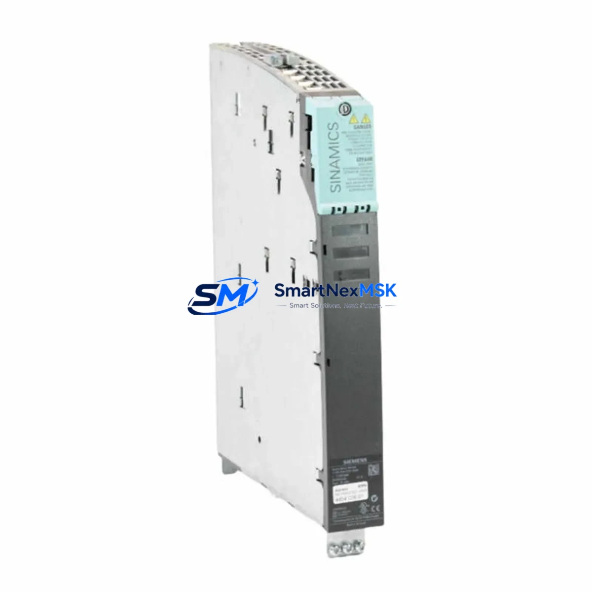
Siemens 6SL3120-2TE21-0AA4 Retrofit-Ready Dual-Axis Motor Module for SINAMICS S120 Control Systems
The Siemens 6SL3120-2TE21-0AA4 is a SINAMICS S120 Dual-Axis Motor Module designed for high-performance servo drive applications in industrial automation environments. As legacy SINAMICS S120 booksize drive lines reach end-of-life or become increasingly difficult to source, the 6SL3120-2TE21-0AA4 serves as a proven retrofit-ready replacement for discontinued dual-axis configurations, enabling engineers to restore full drive functionality without redesigning the control cabinet or rewriting the PLC program from scratch.
This module is engineered for seamless integration into existing SINAMICS S120 booksize drive trains. It connects directly to the Control Unit — typically a CU320-2 DP or CU320-2 PN — via the DRIVE-CLiQ interface, allowing automatic topology recognition and parameter upload from the existing project file. Engineers replacing a failed or obsolete dual-axis module can retain the original STARTER or TIA Portal V15/V16 project, minimizing engineering rework and reducing unplanned downtime to hours rather than days.
Upgrade Compatibility Table
| Parameter | Details |
|---|---|
| SKU / Order Number | 6SL3120-2TE21-0AA4 |
| Series | SINAMICS S120 Booksize |
| Module Type | Dual-Axis Motor Module |
| DC Link Voltage | 600 V DC |
| Output Current (per axis) | 10 A continuous |
| Interface | DRIVE-CLiQ (automatic topology detection) |
| Backplane / Rack Compatibility | SINAMICS S120 Booksize rail mount, shared DC bus |
| Communication Protocol | PROFIBUS DP / PROFINET (via CU320-2) |
| Replacement for | 6SL3120-2TE21-0AA3, 6SL3120-2TE21-0AA0 (earlier revisions) |
| Installation Requirement | 24 V DC auxiliary supply; shared DC bus from Line Module |
| Commissioning Tool | STARTER V5.x / TIA Portal V15 or later with Startdrive |
| Debugging Focus | Motor data set (MDS), encoder feedback (SMC20/SMC30), axis address assignment |
| Warranty | 12 Months — covers functional defects under normal operating conditions |
Retrofit Planning for Existing Automation Systems
When integrating the 6SL3120-2TE21-0AA4 into an existing control cabinet, the retrofit process typically begins with a power capacity audit. The shared DC bus supplied by the Line Module — commonly a 6SL3130-6AE21-0AB1 Active Line Module or a 6SL3130-7TE21-6AA3 Smart Line Module — must have sufficient regenerative capacity to support the dual-axis load profile. Engineers should verify the DC bus voltage stability under peak acceleration torque before finalizing the replacement plan.
Terminal wiring on the 6SL3120-2TE21-0AA4 follows the standard SINAMICS S120 booksize pinout. Motor power connections (U2, V2, W2 per axis) and the 24 V DC electronics supply connect via the standard booksize terminal block, which is mechanically identical to earlier revisions such as the 6SL3120-2TE21-0AA3. This means existing cabinet wiring harnesses can typically be reused without modification, significantly reducing retrofit labor time.
The DRIVE-CLiQ daisy-chain topology must be re-verified after module swap. The CU320-2 DP or CU320-2 PN control unit will perform an automatic topology scan on first power-up. If the project was saved with the previous module’s DRIVE-CLiQ node address, engineers should use STARTER or TIA Portal Startdrive to compare the actual topology against the saved configuration and accept the new component. Encoder feedback modules such as the SMC20 Sensor Module Cabinet-Mounted or SMC30 remain in place and do not require reconfiguration unless the motor data set (MDS) parameters differ between axes.
For systems using PROFIBUS DP communication, the DP address assigned to the CU320-2 DP remains unchanged during a motor module swap — the address is stored in the control unit, not the motor module itself. PROFINET-based systems using CU320-2 PN similarly retain their IP address and device name configuration. This means the upstream PLC — whether a SIMATIC S7-300, S7-400, or S7-1500 — does not require a hardware configuration update in STEP 7 or TIA Portal, provided the GSD/GSDML file version is compatible.
In applications where the 6SL3120-2TE21-0AA4 is replacing a module in a multi-axis drive line, engineers should also inspect the adjacent 6SL3120-1TE23-0AA3 Single-Axis Motor Modules and the 6SL3100-0BE25-5AB0 Braking Module for signs of DC bus overvoltage stress. A failed dual-axis module can sometimes cause transient overvoltage events that stress neighboring components. Replacing the module without inspecting the full drive train may result in repeat failures within weeks of commissioning.
I/O expansion requirements should also be reviewed during the retrofit window. If the existing system relies on a 6ES7321-1BL00-0AA0 Digital Input Module or 6ES7322-1BL00-0AA0 Digital Output Module for axis-level interlocks, verify that the PLC rack has sufficient free slots and that the I/O addresses in the program match the physical slot assignments after any rack reconfiguration. Terminal Module TM31 or TM41 connected via DRIVE-CLiQ can provide additional analog and digital I/O directly at the drive level without consuming PLC rack slots.
HMI screens connected via PROFIBUS or PROFINET — such as those running on a SIMATIC TP700 Comfort or TP1200 Comfort panel — should be tested for correct axis status display after the module swap. Drive fault codes and axis-level diagnostics displayed on the HMI are typically sourced from the CU320-2 via the PLC program; as long as the PLC program and drive parameter set are unchanged, HMI behavior should be transparent to the module replacement.
Downtime Control During System Migration
Minimizing production downtime during a SINAMICS S120 dual-axis module replacement requires a structured pre-commissioning approach. Before the maintenance window begins, engineers should export the full drive parameter set from the existing CU320-2 using STARTER’s Upload to PG/PC function or TIA Portal’s device backup feature. This backup preserves all axis-specific parameters — including speed controller gains, torque limits, encoder resolution settings, and safety function configurations — and allows rapid restoration if the new module requires parameter adjustment.
During the physical swap, the DC bus must be fully discharged before disconnecting the motor module. The SINAMICS S120 booksize design allows hot-swap of individual motor modules only when the system is equipped with a suitable Line Module with pre-charge circuit; in most field installations, a controlled shutdown sequence is required. Engineers should follow the standard lockout/tagout (LOTO) procedure and verify DC bus voltage below 50 V using a calibrated meter before touching any bus bar connections.
After installing the 6SL3120-2TE21-0AA4, the recommended commissioning sequence is: power up the 24 V DC electronics supply first, allow the CU320-2 to complete topology recognition, then apply the DC bus via the Line Module. Use STARTER or TIA Portal to compare the actual drive configuration against the saved project. If the motor data set is identical to the previous module, the drive should be ready for a no-load test run within 30 minutes of power-up. A full load test under production conditions should be performed before releasing the line to production, with particular attention to current limits, speed reference tracking, and encoder feedback signal quality.
For systems where the original program logic cannot be interrupted — such as continuous process lines — a parallel commissioning approach using a spare CU320-2 and the 6SL3120-2TE21-0AA4 pre-configured offline can reduce live switchover time to under 15 minutes. Pre-loading the parameter set and verifying DRIVE-CLiQ topology on the bench before the maintenance window is the most effective strategy for downtime control in critical automation environments.
Retrofit Support FAQ
Q1: Is the 6SL3120-2TE21-0AA4 a direct drop-in replacement for the 6SL3120-2TE21-0AA3?
Yes. The 6SL3120-2TE21-0AA4 is the current revision of the same dual-axis motor module family. The mechanical footprint, DC bus connector, DRIVE-CLiQ port, and motor terminal block are identical to the -0AA3 revision. No wiring changes or mechanical modifications are required. The parameter set from the previous module can be loaded directly without modification in most applications.
Q2: Do I need to update the PLC hardware configuration after replacing the motor module?
No. The SIMATIC S7 PLC communicates with the SINAMICS S120 drive via the CU320-2 control unit, not directly with the motor module. Replacing the motor module does not change the PROFIBUS DP address or PROFINET device name of the CU320-2, so no changes to the PLC hardware configuration in STEP 7 or TIA Portal are required.
Q3: What pre-shipment testing is performed on the 6SL3120-2TE21-0AA4?
Each unit undergoes functional power-on testing prior to shipment, verifying DC bus interface integrity, DRIVE-CLiQ communication handshake, and auxiliary 24 V DC supply circuit. Units are shipped with original or equivalent packaging to prevent transit damage. A 12-month warranty covers all functional defects arising under normal operating conditions from the date of delivery.
Q4: Can this module be used in a SINAMICS S120 chassis format drive system?
No. The 6SL3120-2TE21-0AA4 is specifically designed for the SINAMICS S120 booksize format. It is not compatible with the chassis format drive systems such as the 6SL3310 or 6SL3315 series, which use a different mechanical and electrical interface. For chassis format applications, a separate motor module selection is required.
© 2026 SMARTNEXMSK. All rights reserved.
Original Source: https://smartnexmsk.com
Contact: [email protected] | +86 18259474341



