
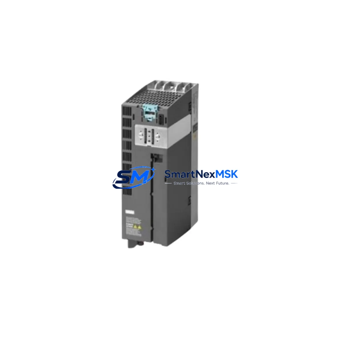
Siemens 6SL3210-1PE12-3AL1 Retrofit-Ready Single Motor Module for SINAMICS S120 Control Systems
The Siemens 6SL3210-1PE12-3AL1 is a booksize-format Single Motor Module within the SINAMICS S120 drive system, rated at 2.3 A output current and designed for precise axis control in multi-axis servo and vector drive applications. As legacy S120 installations age and original modules reach end-of-production status, this unit serves as a direct retrofit replacement — enabling engineers to restore full drive functionality without redesigning the control cabinet or modifying the existing DC link bus architecture.
For retrofit and upgrade projects, the 6SL3210-1PE12-3AL1 slots directly into the existing S120 booksize drive line-up, sharing the same DC bus connector, 24 V control supply rail, and DRIVE-CLiQ communication topology as the original module it replaces. This means the replacement process can be completed without rewiring the motor power terminals or reconfiguring the STARTER / TIA Portal drive project from scratch — a critical advantage when minimizing planned downtime on production lines.
Upgrade Compatibility Table
| Parameter | Specification / Recommendation |
|---|---|
| SKU / Part Number | 6SL3210-1PE12-3AL1 |
| Series | SINAMICS S120 Booksize |
| Module Type | Single Motor Module |
| Output Current | 2.3 A (continuous) |
| DC Link Voltage | 600 V DC (nominal) |
| Communication Interface | DRIVE-CLiQ |
| Control Supply | 24 V DC via system bus rail |
| Mounting Format | Booksize, DIN rail / panel mount |
| Replaces / Compatible With | Earlier 6SL3210-1PE12-x series variants |
| Commissioning Tool | STARTER v4.x / TIA Portal with S120 drive object |
| Firmware Compatibility | SINAMICS S120 firmware V4.7 and above recommended |
| Origin | Germany |
| Warranty | 12 Months — tested and verified before shipment |
Retrofit Planning for Existing Automation Systems
A successful retrofit of the 6SL3210-1PE12-3AL1 requires a structured review of the surrounding drive cabinet components. Before installation, maintenance and commissioning engineers should verify the condition and compatibility of the following elements:
The Active Line Module (ALM) or Smart Line Module (SLM) — such as the 6SL3130-6AE21-0AB1 or 6SL3130-7TE21-6AA3 — must be confirmed to have sufficient DC bus capacity to support the replacement motor module at its rated current. If the line module is also aging, a concurrent replacement should be planned to avoid a second unplanned outage.
The DRIVE-CLiQ hub module (e.g., 6SL3162-2AA00-0AA0) and the DRIVE-CLiQ cables connecting the Control Unit (CU320-2 DP or CU320-2 PN) to the motor module must be inspected for connector wear and signal integrity. A faulty DRIVE-CLiQ cable is a common cause of F07900 faults after module replacement and should be replaced proactively during the retrofit window.
The 24 V DC power supply feeding the control electronics — typically a SITOP PSU100S or equivalent — should be load-tested to confirm it can sustain the inrush demand of the new module during initialization. Undersized 24 V supplies are a frequent but overlooked cause of post-retrofit instability.
Motor feedback devices connected to the SMC (Sensor Module Cabinet-Mounted) — such as the 6SL3055-0AA00-5BA3 SMC20 for incremental encoders or the SMC30 for resolvers — must be re-parameterized in the drive project if the encoder type or cable length has changed. Verify that the motor data set (MDS) in the drive object matches the replacement motor’s nameplate data.
For multi-axis systems, the terminal module TM31 or TM41 handling analog I/O, digital I/O, and safety signals should be audited. Any axis-specific enable signals, speed references, or torque limits wired through these terminal modules must be re-verified against the updated drive topology after the module swap.
If the system uses PROFIBUS DP or PROFINET IO for setpoint exchange with a SIMATIC S7-300, S7-400, or S7-1500 PLC, confirm that the drive’s telegram type (e.g., Standard Telegram 1 or 5) and PZD word mapping remain consistent after replacement. A mismatch in telegram configuration will cause the PLC to report a drive communication fault immediately after restart.
Finally, the Braking Module (if installed, e.g., 6SL3100-1AE31-0AB1) and associated braking resistor should be checked for thermal condition and resistance value. Replacing a motor module without inspecting the braking circuit can expose the new module to overvoltage events during deceleration ramps.
Downtime Control During System Migration
Minimizing production downtime during an S120 motor module replacement requires preparation before the maintenance window begins. The recommended approach is to export the full drive project from STARTER or TIA Portal and back up all drive parameters using the “Upload to PG” function. This preserves the axis configuration, speed controller gains, encoder settings, and safety parameters — allowing the new 6SL3210-1PE12-3AL1 to be commissioned by downloading the saved project rather than re-entering parameters manually.
During the physical swap, the DC bus must be fully discharged before disconnecting the motor module. The S120 system’s DC link capacitors retain dangerous voltage for several minutes after mains disconnection — always verify with a calibrated DC voltmeter before touching bus bar connectors. Label all DRIVE-CLiQ cables and motor power leads before removal to prevent mis-wiring during reinstallation.
After installation, perform a “Restore Factory Settings” on the new module via STARTER, then download the backed-up drive project. Run the motor identification routine (rotating or stationary, depending on load conditions) to optimize current controller parameters for the specific motor. Verify all safety functions (STO, SS1, SLS) are active and responding correctly before releasing the axis to automatic operation.
For systems where a cold spare strategy is preferred, stocking one 6SL3210-1PE12-3AL1 per critical axis — alongside a spare DRIVE-CLiQ cable set and a 24 V fuse block — reduces mean time to repair (MTTR) to under two hours for most booksize S120 installations.
Retrofit Support FAQ
Q1: Is the 6SL3210-1PE12-3AL1 a direct drop-in replacement for earlier S120 Single Motor Module variants?
Yes. The 6SL3210-1PE12-3AL1 is mechanically and electrically compatible with earlier booksize Single Motor Module variants of the same current class. The DC bus connector, DRIVE-CLiQ port, and 24 V supply interface are standardized across the S120 booksize range. A firmware update on the Control Unit may be required if the existing firmware version predates the module’s hardware revision — this is confirmed automatically during DRIVE-CLiQ topology recognition at first power-up.
Q2: What commissioning steps are required after replacing the module on a live production system?
After physical installation, connect via STARTER or TIA Portal and perform a topology comparison. Download the previously backed-up drive project to restore all axis parameters. Execute a stationary motor identification if a rotating identification is not possible under load conditions. Verify encoder feedback, safety function response, and PLC communication before returning the axis to service. Total commissioning time for a prepared engineer is typically 1–3 hours.
Q3: How is compatibility with the existing motor and encoder verified before ordering?
Provide the motor order number, encoder type (incremental TTL, EnDat, resolver), and the existing drive firmware version. Our technical team will cross-reference the motor data set requirements against the 6SL3210-1PE12-3AL1 specifications and confirm compatibility before shipment. All units are function-tested on an S120 test bench and shipped with a test report.
Q4: What does the 12-month warranty cover?
The 12-month warranty covers all manufacturing defects, component failures, and functional faults under normal operating conditions. Each unit is powered on, DRIVE-CLiQ enumerated, and load-tested before dispatch. In the event of a warranty claim, we provide advance replacement to minimize your downtime, with return logistics coordinated by our support team. Warranty is valid from the date of confirmed delivery.
© 2026 SMARTNEXMSK. All rights reserved.
Original Source: https://smartnexmsk.com
Contact: [email protected] | +86 18259474341



