
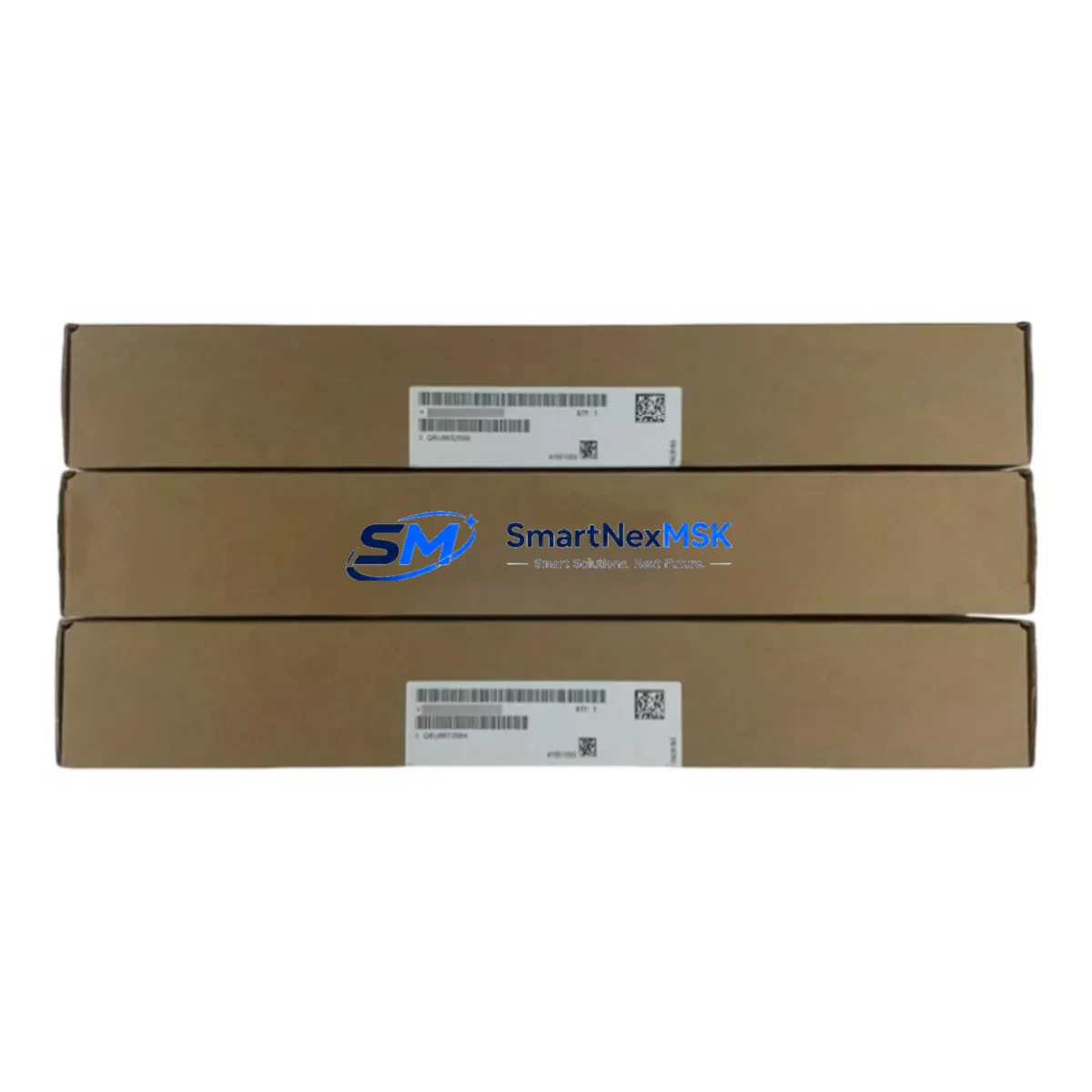
Siemens 6SL3351-6TE32-6AA3 Spare for S120 Automation: Spare Replacement & Industrial Downtime Risk Control
The Siemens 6SL3351-6TE32-6AA3 is the CU320-2 DP Control Unit for the SINAMICS S120 drive system — one of the most widely deployed multi-axis servo and vector drive platforms in industrial automation. As a central intelligence component governing speed, torque, and positioning across multiple drive axes, the CU320-2 DP is a high-criticality spare that maintenance engineers must keep available to prevent extended production downtime. This listing provides a maintenance-ready, original spare with full compatibility verification, pre-shipment functional testing, and a 12-month warranty.
Whether you are managing a planned overhaul, responding to an unscheduled fault, or building a strategic spare parts inventory for aging S120 installations, this unit ships from verified stock with documentation support to accelerate your site restoration workflow.
Spare Maintenance Table
| Parameter | Specification |
|---|---|
| Part Number (SKU) | 6SL3351-6TE32-6AA3 |
| Description | CU320-2 DP Control Unit |
| Series | SINAMICS S120 |
| Brand | Siemens |
| Communication Interface | PROFIBUS DP (up to 12 Mbit/s) |
| Encoder Interfaces | 3 × DRIVE-CLiQ, 1 × HTL/TTL encoder input |
| Digital Inputs / Outputs | 12 DI / 8 DO (onboard) |
| Supply Voltage | 24 V DC (via SINAMICS S120 Power Module or Control Supply Module) |
| Firmware Compatibility | SINAMICS S120 firmware V4.x and above |
| Mounting | Booksize format, DIN rail / panel mount via S120 chassis |
| Operating Temperature | 0 °C to +55 °C (derating above 45 °C) |
| Protection Class | IP20 |
| Country of Origin | Germany |
| Compatibility | SINAMICS S120 Booksize Power Modules, Motor Modules, and Line Modules |
| Pre-shipment Testing | Functional power-on test performed before dispatch |
| Warranty | 12 Months |
| Condition | Original, unused or refurbished-to-spec |
Maintenance Planning for Continuous Operation
When a CU320-2 DP fault is diagnosed — whether through a SINAMICS alarm code, a PROFIBUS communication loss, or a complete axis shutdown — the replacement workflow extends well beyond swapping the control unit itself. Experienced maintenance engineers treat this event as a trigger for a broader cabinet inspection to prevent repeat failures and ensure system stability after restart.
Before commissioning the replacement 6SL3351-6TE32-6AA3, inspect the 24 V DC Control Supply Module (e.g., 6SL3100-1BE21-3AA0) that powers the CU320-2 DP. A degraded or undersized supply is a common root cause of control unit faults and will damage a new unit if not addressed. Verify output voltage stability under load and check for ripple or dropout events logged in the drive diagnostics.
Next, audit all DRIVE-CLiQ cables connecting the CU320-2 DP to downstream Motor Modules and Line Modules. Damaged or intermittently connected DRIVE-CLiQ links generate topology errors that can be misdiagnosed as control unit failures. Replace any cables showing physical wear, bent connectors, or signal integrity issues. Similarly, inspect the PROFIBUS DP connector and termination resistor at the CU320-2 DP port — a missing or incorrect termination is a frequent source of communication instability in multi-node PROFIBUS networks.
For sites running SINAMICS S120 Motor Modules (single-axis or double-axis booksize units), confirm that each module’s firmware version is compatible with the replacement CU320-2 DP firmware. Mismatched firmware between the control unit and power modules can prevent the drive from entering the ready state. If the site uses a Siemens SIMATIC S7-300 or S7-400 PLC as the master controller, verify the PROFIBUS GSD file and station address configuration before going live.
Cabinet-level inspection should also cover the 24 V DC fuse and circuit breaker protecting the control supply rail, terminal block integrity on the DI/DO wiring, and the condition of the CompactFlash card (if used for parameter backup on older CU320-2 DP variants). For systems with Siemens SMC30 Sensor Module Cabinet-Mounted units handling encoder feedback, verify that encoder signal levels and cable shielding are intact — encoder faults are frequently masked by control unit alarms.
If the installation includes a Siemens OP panel or SIMATIC HMI connected via PROFIBUS or Ethernet, test the HMI communication link after the control unit replacement to confirm that drive status visualization and parameter access are restored. Sites using signal isolators or PROFIBUS repeaters in long-cable runs should also verify repeater power and signal levels as part of the post-replacement commissioning checklist.
Maintaining a minimum spare inventory of one CU320-2 DP per S120 installation — alongside a matched set of DRIVE-CLiQ cables, a spare CompactFlash card with the latest parameter backup, and a tested 24 V supply module — is the recommended strategy for facilities where unplanned downtime carries significant production cost.
Site Replacement Workflow
Step 1 — Fault Isolation: Record all active SINAMICS alarm and fault codes from the drive diagnostics before powering down. Note the firmware version displayed on the existing CU320-2 DP. This information is required for firmware matching and post-replacement parameter restore.
Step 2 — Safe Isolation: Follow your site LOTO (Lockout/Tagout) procedure. Isolate the S120 Line Module from the AC supply and discharge the DC link capacitors per the Siemens safety guidelines (minimum 5-minute wait after isolation, verify with a calibrated voltmeter).
Step 3 — Physical Replacement: Disconnect all DRIVE-CLiQ cables, PROFIBUS connector, 24 V supply connector, and DI/DO terminal blocks from the existing CU320-2 DP. Remove the unit from the booksize chassis. Install the replacement 6SL3351-6TE32-6AA3 and reconnect all connectors in reverse order. Ensure DRIVE-CLiQ cables are seated and latched fully.
Step 4 — Firmware & Parameter Restore: If the replacement unit ships with a different firmware version, update via STARTER or SINAMICS Startdrive before loading parameters. Restore the parameter backup from the CompactFlash card or from a STARTER project file. Verify all axis configurations, encoder assignments, and PROFIBUS station addresses.
Step 5 — Commissioning & Test: Power up in sequence — Control Supply Module first, then Line Module, then Motor Modules. Confirm no active faults. Run a low-speed jog test on each axis before returning to production speed. Document the replacement in the site maintenance log.
This workflow minimizes restart time and reduces the risk of secondary faults caused by incomplete commissioning — a common source of repeat callouts on S120 systems.
Spare Parts Support FAQ
Q1: Is the 6SL3351-6TE32-6AA3 compatible with all SINAMICS S120 booksize configurations?
The CU320-2 DP is designed for SINAMICS S120 booksize format systems and is compatible with S120 Line Modules, Motor Modules, and Braking Modules in booksize format. It is not directly interchangeable with chassis-format S120 components or with the CU310-2 single-axis control unit. Confirm your existing hardware topology before ordering. Our technical team can assist with compatibility verification based on your existing drive order numbers.
Q2: What pre-shipment testing is performed on this unit?
Every unit undergoes a functional power-on test prior to dispatch. We verify that the control unit initializes correctly, that DRIVE-CLiQ ports are active, and that the unit is free from physical damage or component degradation. A test report is available upon request. Units are packed in anti-static packaging with protective foam to prevent transit damage.
Q3: How should I manage spare parts inventory for aging S120 installations?
For S120 systems approaching or beyond 10 years of service, we recommend holding at minimum one CU320-2 DP, one matched 24 V Control Supply Module, a set of DRIVE-CLiQ cables in the lengths used on your installation, and a current parameter backup on a spare CompactFlash card. As Siemens transitions older S120 variants to limited availability, securing spares proactively avoids extended lead times during emergency procurement. We offer long-term supply agreements for facilities managing multiple S120 installations.
Q4: What does the 12-month warranty cover?
The 12-month warranty covers manufacturing defects and functional failure under normal operating conditions. It does not cover damage resulting from incorrect installation, overvoltage events, or operation outside the specified environmental parameters. In the event of a warranty claim, we provide a replacement unit or repair service with a target turnaround of 5 business days. Contact our technical support team with the unit serial number and fault description to initiate a claim.
© 2026 SMARTNEXMSK. All rights reserved.
Original Source: https://smartnexmsk.com
Contact: [email protected] | +86 18259474341



