
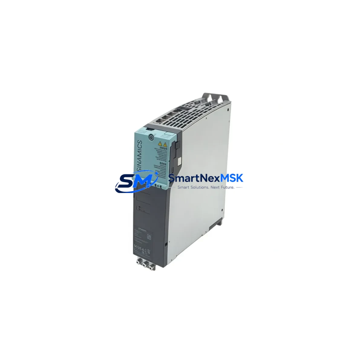
Siemens 6SL3420-2TE15-0AA1 Retrofit-Ready Dual-Axis Module for SINAMICS S120 Control Systems
The Siemens 6SL3420-2TE15-0AA1 is a SINAMICS S120 Booksize Dual-Axis Motor Module rated at 5A continuous output current per axis. Designed for high-performance servo and vector drive applications, this module is a proven retrofit and replacement solution for aging S120 Booksize drive lines across manufacturing, packaging, printing, and material handling industries. Whether you are replacing a failed unit, upgrading a legacy drive cabinet, or migrating from an earlier SINAMICS S120 configuration, the 6SL3420-2TE15-0AA1 delivers verified compatibility with existing DC link bus systems, DRIVE-CLiQ communication topology, and STARTER/TIA Portal commissioning environments.
This module slots directly into existing S120 Booksize racks alongside the Control Unit CU320-2 PN or CU320-2 DP, sharing the DC bus with the Line Module (Active Line Module or Smart Line Module) already installed in the cabinet. No structural cabinet modifications are required for a like-for-like replacement. The module communicates via DRIVE-CLiQ, enabling automatic component recognition and parameter upload from the existing project file, significantly reducing commissioning time during planned or emergency retrofits.
Upgrade Compatibility Table
| Parameter | Details |
|---|---|
| SKU / Order Number | 6SL3420-2TE15-0AA1 |
| Series | SINAMICS S120 Booksize |
| Module Type | Dual-Axis Motor Module |
| Output Current (per axis) | 5A |
| DC Link Voltage | 600V DC (nominal) |
| Communication Interface | DRIVE-CLiQ (×2 per axis) |
| Installation Format | Booksize, DIN rail / panel mount |
| Replaces / Compatible With | Earlier 6SL342x Dual-Axis variants; S120 Booksize line |
| Control Unit Compatibility | CU320-2 PN, CU320-2 DP |
| Commissioning Tool | STARTER v4.x / TIA Portal V15+ |
| Firmware Upgrade Required | Verify CU firmware ≥ V4.7 SP9 |
| Terminal / Connector | X1 DC bus bar; X200/X201 DRIVE-CLiQ; X400 motor power |
| Country of Origin | Germany |
| Warranty | 12 Months |
Retrofit Planning for Existing Automation Systems
A successful retrofit of the 6SL3420-2TE15-0AA1 into an existing S120 Booksize cabinet begins with a thorough audit of the current drive topology. Engineers should first verify the DC link capacity of the installed Active Line Module (ALM) or Smart Line Module (SLM) — typically a 6SL3130-series or 6SL3120-series unit — to confirm it can support the combined peak current demand of all Motor Modules on the shared bus. Undersized line modules are a common cause of nuisance trips after a module swap.
Next, inspect the DRIVE-CLiQ wiring chain. The 6SL3420-2TE15-0AA1 occupies two DRIVE-CLiQ ports on the Control Unit (one per axis), and the daisy-chain sequence must be preserved or re-mapped in the project file. If the existing CU320-2 PN is running firmware below V4.7 SP9, a firmware update via STARTER or TIA Portal is recommended before inserting the new module to avoid topology mismatch faults (F01375 / F07220).
Terminal block and motor power connector verification is equally critical. The X400 motor power connector pinout on the 6SL3420-2TE15-0AA1 follows the standard S120 Booksize layout, but cable cross-sections and shield termination at the cabinet gland plate should be re-checked against the motor nameplate current. For multi-axis gantry or coordinated motion applications, the Sensor Module Cabinet-Mounted SMC30 or SMC20 encoder interface modules must also be confirmed compatible with the encoder type (TTL, HTL, resolver, or EnDat 2.2) used on the connected servo motors.
When the replacement module is physically installed, use STARTER’s “Automatic Configuration” function or TIA Portal’s “Go Online” topology scan to detect the new component. The system will prompt for parameter acceptance — at this stage, compare the loaded parameter set against the backed-up project archive to identify any axis-specific tuning values (speed controller Kp/Tn, current limits, ramp times) that must be restored manually. For sites using SIMATIC S7-300 or S7-400 PLCs communicating with the drive via PROFIBUS DP through the CU320-2 DP, verify that the GSD file version and DP slave address remain unchanged after the swap to avoid communication loss on the fieldbus segment.
Cabinet-level accessories that are commonly replaced or upgraded in the same service window include the 24V DC SITOP PSU8200 power supply module feeding the Control Unit and I/O, the Terminal Module TM31 for analog and digital I/O expansion, and the Braking Module with external braking resistor if dynamic braking is part of the machine cycle. Documenting the pre-retrofit state of all these components — including their firmware versions and parameter checksums — is best practice for ISO-compliant maintenance records.
Downtime Control During System Migration
Minimizing production downtime during a drive module replacement requires preparation that begins well before the maintenance window. The most effective approach is to perform a full parameter backup using STARTER’s “Save Project to PG/PC” function or TIA Portal’s “Upload from Device” while the original module is still operational. This backup captures all axis parameters, safety function configurations, and communication settings, and serves as the restore baseline if commissioning of the replacement module encounters unexpected deviations.
For lines where even a brief unplanned stop is costly, consider staging the 6SL3420-2TE15-0AA1 as a pre-commissioned hot spare: connect it to a bench test rig with a matching CU320-2 PN and a small Line Module, load the backed-up project, and verify axis response before the scheduled maintenance window. This approach reduces in-cabinet commissioning time to a physical swap and a topology confirmation, typically achievable within a two-hour planned shutdown.
During the swap, isolate the DC bus by switching off the Line Module and confirming DC link voltage has discharged below 50V (use a calibrated meter — do not rely solely on the LED indicator). Re-torque all DC bus bar connections to the specified 6 Nm and verify DRIVE-CLiQ connector latches are fully engaged. After power-up, monitor the CU320-2 diagnostics buffer for the first 10 minutes of operation to catch any latent faults before returning the machine to production. Retaining the original module as a tested spare — rather than returning it immediately — provides an additional safety net during the post-retrofit observation period.
Retrofit Support FAQ
Q1: Is the 6SL3420-2TE15-0AA1 a direct drop-in replacement for other 6SL3420-2TE1x variants?
A: The 6SL3420-2TE15-0AA1 (5A per axis) is mechanically and electrically compatible with other S120 Booksize Dual-Axis Motor Modules of the same frame size. However, current rating differences between variants must be verified against the motor nameplate and the ALM/SLM capacity. Always confirm the order number suffix matches the required current class before installation.
Q2: What commissioning steps are required after installing the replacement module?
A: After physical installation, connect via STARTER or TIA Portal and perform a topology scan. Accept the new component, restore the backed-up parameter set, and run a no-load test cycle on each axis. Verify speed reference tracking, current limits, and safety function acknowledgment (STO/SS1 if configured) before returning to production.
Q3: How do I verify terminal wiring compatibility before powering up?
A: Cross-reference the existing cabinet wiring diagram against the 6SL3420-2TE15-0AA1 hardware installation manual (Siemens document A5E03574083). Pay particular attention to X400 motor power phasing (U2/V2/W2 per axis), PE bonding, and the 24V DC supply to X124. Incorrect phasing will cause motor rotation direction faults (F07220) at first run.
Q4: What does the 12-month warranty cover?
A: All units supplied by SMARTNEXMSK carry a 12-month warranty covering manufacturing defects and functional failures under normal operating conditions. Each module undergoes pre-shipment functional testing. Warranty claims are supported with replacement dispatch within agreed lead times. Contact [email protected] for RMA procedures and technical support.
© 2026 SMARTNEXMSK. All rights reserved.
Original Source: https://smartnexmsk.com
Contact: [email protected] | +86 18259474341



