
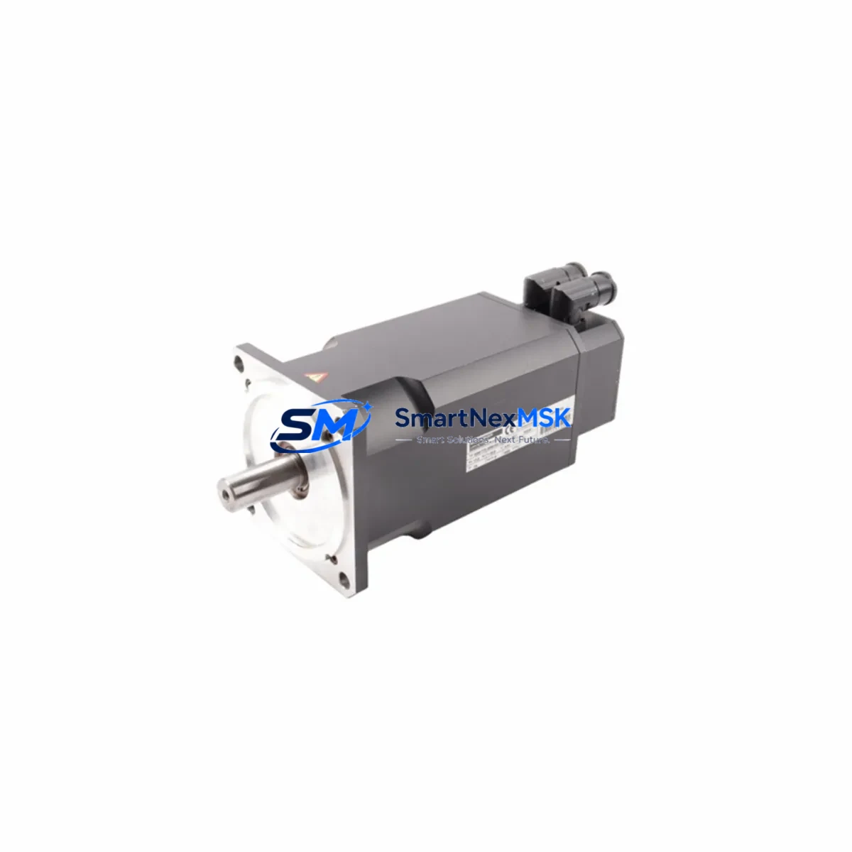
Siemens 6SM56-S-3000-09-J Retrofit-Ready AC Servo Drive: Compatible Modernization & Legacy SIMODRIVE System Upgrade
The Siemens 6SM56-S-3000-09-J is a high-performance AC servo drive module from the SIMODRIVE series, engineered for precision motion control in demanding industrial environments. As legacy SIMODRIVE installations approach end-of-life and original spare parts become increasingly scarce, the 6SM56-S-3000-09-J has emerged as a critical retrofit and replacement component for engineers tasked with modernizing aging CNC machine tools, transfer lines, and multi-axis servo systems without full system overhauls.
This unit supports smooth integration into existing SIMODRIVE 611 and SIMODRIVE 611U control architectures, making it a preferred choice for maintenance engineers who need to restore machine availability quickly while preserving existing program logic, HMI screens, and fieldbus configurations. Whether you are replacing a failed axis module, upgrading power capacity, or migrating from an obsolete drive variant, the 6SM56-S-3000-09-J delivers the electrical and mechanical compatibility required for a controlled, low-risk retrofit.
Upgrade Compatibility Table
| Parameter | Details |
|---|---|
| Compatible Series | SIMODRIVE 611, SIMODRIVE 611U, SIMODRIVE 611D |
| Backplane Interface | Standard SIMODRIVE bus connector; compatible with existing 611-series rack and subrack assemblies |
| Power Supply Compatibility | Works with SIMODRIVE 611 infeed/regenerative feedback modules (e.g., 6SN1145 series); verify DC bus voltage and current capacity before installation |
| Communication Protocol | PROFIBUS-DP compatible; supports legacy SINUMERIK 840D / 810D CNC controller integration |
| Terminal Wiring | Standard X1/X2 motor power terminals and encoder feedback connector; verify pin-out against existing cable harness before replacement |
| Module Address | Axis address configurable via SIMODRIVE parameter set; re-parameterization required after swap |
| Replacement Recommendation | Direct replacement for same-series failed axis modules; cross-reference with 6SN1123 and 6SN1124 drive module families for equivalent power ratings |
| Commissioning Focus | Motor data set upload, encoder calibration, current controller tuning, and PROFIBUS node address verification |
| Installation Requirement | DIN rail or subrack mounting; confirm slot position and bus termination resistor placement |
| Warranty | 12-Month Warranty — covers manufacturing defects and functional failure under normal operating conditions |
Retrofit Planning for Existing Automation Systems
A successful retrofit of the 6SM56-S-3000-09-J begins well before the physical swap. Engineers should start by auditing the existing SIMODRIVE 611 subrack to confirm available slot positions, DC bus load distribution, and the current state of the infeed module — typically a 6SN1145-series regenerative supply unit. The DC bus must have sufficient headroom to support the replacement axis module at peak torque demand, particularly in multi-axis configurations where several 6SN1123 or 6SN1124 drive modules share a common bus.
Terminal wiring is a frequent source of commissioning delays. Before disconnecting the failed unit, photograph and document all X1 motor power connections, X2 encoder feedback wiring, and any auxiliary I/O signals routed through the drive’s control terminals. The 6SM56-S-3000-09-J uses the standard SIMODRIVE terminal layout, but cable harnesses on older machines may have been field-modified, making documentation essential. Pay particular attention to the encoder cable shield grounding and the motor holding brake circuit if present.
The backplane bus connector must be inspected for bent pins or corrosion before seating the replacement module. In older SIMODRIVE 611 racks, the bus termination resistor module at the end of the subrack should also be verified — a missing or damaged terminator is a common cause of communication faults after module replacement. If the system uses a SINUMERIK 840D sl or 810D CNC controller, the NCK (Numerical Control Kernel) will need to recognize the new drive module via a drive configuration download using SIMATIC STEP 7 or STARTER commissioning software.
For systems that include a SIMATIC S7-300 or S7-400 PLC coordinating auxiliary axes or peripheral I/O, verify that the PLC program’s axis assignment and drive enable logic remain consistent after the swap. If the retrofit also involves upgrading communication from legacy PROFIBUS-DP to PROFINET, additional gateway hardware such as a PN/DP coupler may be required. HMI screens built on SIMATIC WinCC or OP/TP panel series should be reviewed to confirm that axis status displays and alarm messages reference the correct drive address after re-parameterization.
Where the retrofit scope extends to I/O expansion — for example, adding digital input/output modules to support new safety interlocks or position sensors — ET 200S or ET 200SP distributed I/O stations can be integrated into the existing PROFIBUS segment without disrupting the servo drive configuration. Power distribution within the control cabinet should also be reviewed: the 24 VDC control supply feeding the drive’s electronics section must be stable and adequately rated, especially if additional modules are being added to the same rail.
Downtime Control During System Migration
Minimizing unplanned downtime is the primary concern for any production facility undertaking a SIMODRIVE retrofit. The recommended approach is to prepare the replacement 6SM56-S-3000-09-J module fully before the maintenance window begins. This includes uploading the existing drive parameter set from the SINUMERIK controller or from a backup file created with STARTER or SIMOCOM U software, so that the new module can be pre-configured offline and loaded immediately upon installation.
Before powering down the machine, back up the complete NCK and PLC program from the SINUMERIK 840D or 810D controller to a CF card or network share. This protects against data loss if the controller’s battery-backed SRAM is compromised during the power cycle. If the machine has been running a proven production program for years, this backup is the single most important step in the entire retrofit process.
During the physical swap, follow a structured sequence: isolate the DC bus, discharge the capacitor bank (allow a minimum of five minutes after power-off), remove the failed module, inspect the subrack and bus connector, seat the replacement unit, and restore all wiring connections before re-energizing. After power-up, perform a controlled jog test on the affected axis at reduced speed before returning the machine to automatic cycle. Verify encoder feedback signals, current controller response, and any safety-relevant functions such as safe torque off (STO) before resuming production. This structured approach typically allows a trained technician to complete a single-axis SIMODRIVE module replacement within a two-to-four hour maintenance window, keeping production disruption to a minimum.
Retrofit Support FAQ
Q1: Is the 6SM56-S-3000-09-J a direct drop-in replacement for other SIMODRIVE 611 axis modules?
A: The 6SM56-S-3000-09-J is designed for compatibility within the SIMODRIVE 611 and 611U platform. It shares the same backplane bus interface and subrack form factor as other modules in the 6SN1123 and 6SN1124 families. However, power rating, current output, and motor data set must be verified against the original module specification before installation. A parameter re-upload is always required after replacement.
Q2: What commissioning steps are required after installing the replacement module?
A: After physical installation, connect the STARTER or SIMOCOM U commissioning tool via the PROFIBUS or USB service interface. Upload the backed-up drive parameter set, verify the motor data set (motor type, encoder type, rated current, and speed), set the PROFIBUS node address to match the original configuration, and perform a motor identification run if the motor data set is unavailable. Finally, test all axis movements in jog mode before enabling automatic operation.
Q3: How do I verify wiring compatibility before powering up?
A: Compare the terminal layout of the 6SM56-S-3000-09-J against the original module’s wiring diagram. Check X1 (motor power: U2, V2, W2, PE), X2 (encoder feedback: differential signals, supply voltage, and shield), and any auxiliary control terminals. Use a continuity tester to verify cable integrity before reconnection. Confirm that the motor holding brake circuit (if present) is correctly wired to the brake output terminals and that the brake release voltage matches the drive’s output specification.
Q4: What does the 12-month warranty cover, and what is the shipping lead time?
A: The 12-month warranty covers manufacturing defects and functional failures under normal operating conditions from the date of shipment. It does not cover damage resulting from incorrect installation, overvoltage events, or environmental contamination. All units undergo pre-shipment functional testing before dispatch. Standard lead time is 3–7 business days for in-stock units, with expedited options available for urgent production recovery situations. Contact our sales team for current stock availability and delivery scheduling.
© 2026 SMARTNEXMSK. All rights reserved.
Original Source: https://smartnexmsk.com
Contact: [email protected] | +86 18259474341



