
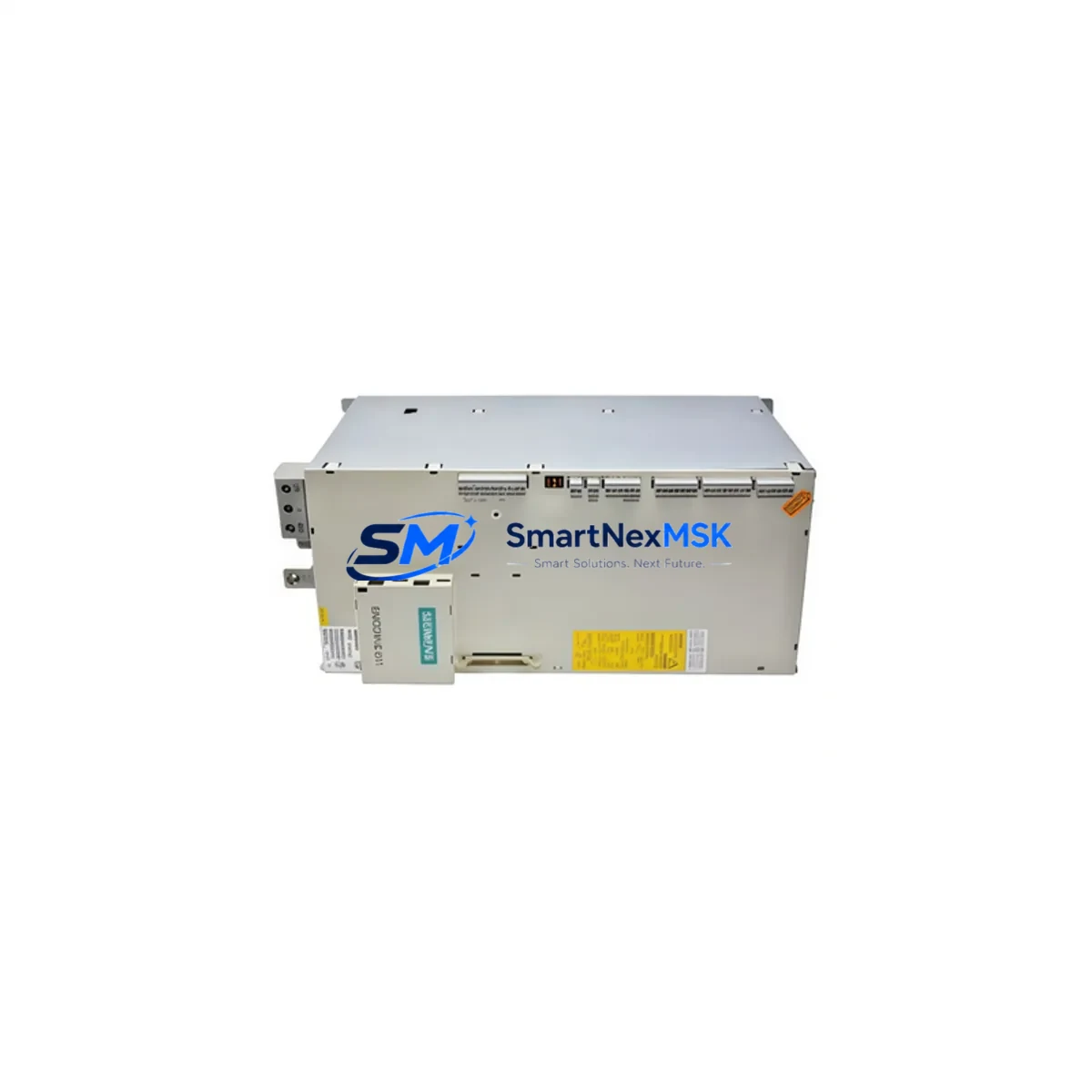
Siemens 6SN1145-1BA02-0CA2 Spare for SIMODRIVE 611 Automation
The Siemens 6SN1145-1BA02-0CA2 is an original infeed/regenerative feedback power module designed for the SIMODRIVE 611 drive system — one of Siemens’ most widely deployed servo drive platforms in CNC machining centers, transfer lines, and precision manufacturing automation. When this module fails or degrades, the entire drive cabinet loses its DC bus supply, resulting in immediate machine downtime. Stocking a verified replacement unit is the single most effective measure a maintenance team can take to minimize mean time to repair (MTTR) and protect production continuity.
This unit is sourced as an original Siemens spare, fully tested prior to dispatch, and backed by a 12-month warranty covering manufacturing defects and functional failure under normal operating conditions. Each unit undergoes pre-shipment functional verification to confirm output voltage stability, regenerative feedback capability, and protection circuit integrity before leaving our facility.
Spare Maintenance Table
| Parameter | Specification |
|---|---|
| Part Number / SKU | 6SN1145-1BA02-0CA2 |
| Product Type | Infeed / Regenerative Feedback Power Module |
| Series | SIMODRIVE 611 |
| Brand | Siemens |
| Origin | Germany (DE) |
| Input Voltage | 3-phase AC 380–480 V ±10% |
| DC Bus Output | 600 V DC nominal |
| Rated Power | ~16 kW infeed / regenerative |
| Cooling | Forced air (internal fan) |
| Protection Class | IP20 (cabinet installation) |
| Compatible Drive Modules | SIMODRIVE 611 axis/spindle drive modules (6SN11xx series) |
| Compatible Controllers | SINUMERIK 840D, 810D, 802D; SIMATIC S7 with SIMODRIVE interface |
| Installation | DIN rail / backplane slot, standard SIMODRIVE 611 cabinet |
| Operating Temperature | 0 °C to +40 °C (derate above 40 °C) |
| Warranty | 12 Months — functional warranty, manufacturing defects covered |
| Pre-Shipment Test | DC bus output, regenerative feedback, protection circuit verification |
Maintenance Planning for Continuous Operation
When a SIMODRIVE 611 infeed module such as the 6SN1145-1BA02-0CA2 is scheduled for replacement — whether during planned shutdown maintenance or emergency fault response — experienced maintenance engineers treat the event as an opportunity to inspect the entire drive cabinet. The infeed module sits at the heart of the DC bus distribution, and its failure mode often places stress on adjacent components that may not immediately show fault codes.
Begin with the line filter module (typically a 6SN1111-series component) upstream of the infeed module: check for signs of overheating, capacitor bulge, or insulation breakdown. Inspect the monitoring module (6SN1145-1AA0x series) that supervises DC bus voltage and triggers protective shutdowns — a degraded monitoring module can cause nuisance trips or, worse, fail to protect the bus during a real fault. Verify the axis drive modules (6SN1123 or 6SN1124 series) connected to the same DC bus rail; a failing infeed module often causes transient overvoltage events that stress the drive module capacitors.
Check all 24 V DC auxiliary power supplies feeding the control electronics — the SIMODRIVE 611 control boards require stable 24 V for encoder interfaces, enable signals, and communication. Inspect terminal blocks and bus connectors on the backplane for fretting corrosion, especially in high-vibration environments. Review the encoder cables and feedback connectors (6FX series shielded cables) for chafing or connector pin damage, as encoder signal loss is a common secondary fault after a power module replacement.
For systems integrated with a SINUMERIK 840D or 810D CNC controller, verify the NCU (Numerical Control Unit) and its PROFIBUS or DRIVE-CLiQ communication links to the drive modules after power restoration. If the cabinet includes a SIMATIC S7-300 or S7-400 PLC for auxiliary I/O control, confirm that the SM321/SM322 digital I/O modules and any CP343 communication processors are functioning correctly post-restart. Where signal isolation is required between the drive cabinet and field sensors, inspect signal isolators and relay output modules for contact wear. Finally, verify the main circuit breaker and contactor ratings against the infeed module’s inrush current specification to prevent nuisance tripping during re-energization.
Site Replacement Workflow
Step 1 — Fault Isolation: Record all active alarms on the SINUMERIK or SIMATIC HMI panel before de-energizing. Note DC bus voltage readings and any asymmetric phase fault indicators. This data guides post-replacement verification.
Step 2 — Safe De-energization: Follow LOTO (Lockout/Tagout) procedure. Discharge the DC bus capacitors fully (minimum 5 minutes after main power off, verify with a calibrated meter) before touching any bus bar or module connector.
Step 3 — Module Removal: Disconnect the AC line input terminals, DC bus connectors, 24 V auxiliary supply, and the control connector (X151/X161 depending on variant). Note cable routing and label all connectors before removal.
Step 4 — Replacement Installation: Install the 6SN1145-1BA02-0CA2 replacement into the same backplane slot. Reconnect all terminals in reverse order. Torque AC input terminals to specification (refer to Siemens SIMODRIVE 611 installation manual, document 6SN1197-0AA00-0BP8 or equivalent).
Step 5 — Power-Up and Verification: Restore power in stages. Confirm DC bus voltage stabilizes at 600 V DC ±5%. Clear all stored faults on the CNC/PLC. Run a no-load axis jog test before resuming production. Document the replacement in the machine maintenance log with date, replaced part number, and technician ID.
This workflow minimizes re-work risk and ensures the replacement unit is confirmed operational before the machine returns to production — protecting both the equipment and the replacement spare from secondary damage.
Spare Parts Support FAQ
Q1: What is the warranty coverage for the 6SN1145-1BA02-0CA2?
A: This unit carries a 12-month warranty from the date of dispatch, covering manufacturing defects and functional failure under normal operating conditions. The warranty does not cover damage resulting from incorrect installation, overvoltage events beyond specification, or physical impact.
Q2: How do I verify compatibility before installation?
A: Confirm the existing unit’s nameplate matches SKU 6SN1145-1BA02-0CA2 exactly, including the full order number suffix. Cross-reference with the SIMODRIVE 611 system configuration documentation for your machine. If you are substituting from a different sub-variant (e.g., -0BA2 vs -0CA2), contact our technical team with your machine’s drive configuration file before ordering.
Q3: Is the unit tested before shipment?
A: Yes. Every unit undergoes pre-shipment functional testing covering DC bus output voltage, regenerative feedback circuit, and internal protection relay operation. A test record is available upon request for quality-critical applications.
Q4: Can you support long-term or repeat supply for maintenance contracts?
A: Yes. We support scheduled maintenance contracts and blanket purchase orders for facilities managing multiple SIMODRIVE 611 cabinets. Contact our team to discuss lead times, reserved stock arrangements, and volume pricing for ongoing spare parts programs.
© 2026 SMARTNEXMSK. All rights reserved.
Original Source: https://smartnexmsk.com
Contact: [email protected] | +86 18259474341



