
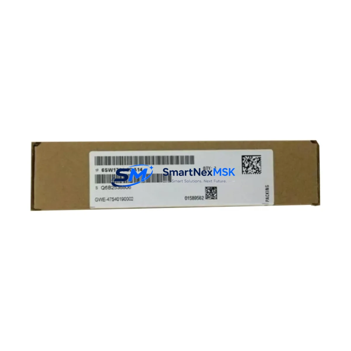
Siemens 6SW1701-0DA14V98113-A1680-A1-4.8 Retrofit-Ready Drive Control for SIMOVERT Control Systems
The Siemens 6SW1701-0DA14V98113-A1680-A1-4.8 is a retrofit-ready drive control module engineered for seamless integration into existing SIMOVERT frequency converter platforms. As legacy SIMOVERT MC and SIMOVERT MASTERDRIVES systems approach end-of-life, this module provides a validated, drop-in compatible upgrade path that preserves existing cabinet wiring, backplane interfaces, and drive parameter sets — dramatically reducing engineering rework and unplanned downtime during modernization projects.
Designed for industrial environments where control continuity is non-negotiable, the 6SW1701-0DA14V98113-A1680-A1-4.8 supports both USS protocol and PROFIBUS-DP communication, making it directly interoperable with upstream Siemens SIMATIC S7-300 and S7-400 PLCs, as well as SIMATIC HMI panels such as the TP177 and MP277 series. Engineers migrating from older SIMOVERT compact units will find that the module’s parameter structure aligns with STARTER and DriveMonitor commissioning tools, enabling rapid re-commissioning without full program rewrites.
For retrofit planners, the 6SW1701-0DA14V98113-A1680-A1-4.8 is particularly valuable in scenarios involving I/O expansion, where existing terminal blocks and DIN rail assemblies must be preserved. The module’s terminal assignment is compatible with standard 24 VDC control voltage rails, and its backplane connector geometry matches the SIMOVERT compact chassis family, eliminating the need for adapter plates or custom cable harnesses in most installations.
Upgrade Compatibility Table
| Parameter | Details |
|---|---|
| SKU / Part Number | 6SW1701-0DA14V98113-A1680-A1-4.8 |
| Brand / Manufacturer | Siemens |
| Series | SIMOVERT (Compact / MASTERDRIVES) |
| Module Function | Drive Control Module — frequency converter control board |
| Communication Interfaces | USS Protocol, PROFIBUS-DP |
| Control Voltage | 24 VDC (standard SIMOVERT rail) |
| Backplane / Rack Interface | Compatible with SIMOVERT compact chassis backplane |
| Replacement Compatibility | Direct replacement for equivalent SIMOVERT drive control boards; verify firmware version before swap |
| Commissioning Tool | STARTER, DriveMonitor (Siemens) |
| HMI Compatibility | SIMATIC TP177, MP277, OP177 series |
| PLC Compatibility | SIMATIC S7-300, S7-400 via PROFIBUS-DP |
| Installation Requirement | Match module address settings to existing drive configuration; back up parameters before replacement |
| Commissioning Notes | Upload saved parameter set via DriveMonitor; verify motor data, ramp times, and I/O assignments post-swap |
| Warranty | 12 Months — covers manufacturing defects; includes pre-shipment functional test |
| Origin | Germany (OEM) |
Retrofit Planning for Existing Automation Systems
A successful retrofit using the 6SW1701-0DA14V98113-A1680-A1-4.8 begins with a thorough audit of the existing control cabinet. Before any hardware swap, engineers should document the current drive parameter set using DriveMonitor or STARTER software, capturing motor nameplate data, ramp-up/ramp-down times, current limits, and all active I/O assignments. This parameter backup is the single most important step in protecting the existing control logic and avoiding extended commissioning time on site.
Power supply capacity must be verified before installation. The SIMOVERT compact platform typically draws control power from a dedicated 24 VDC SITOP power supply module. If the existing SITOP PSU is undersized or aging, it is advisable to replace it concurrently with the drive control board to prevent nuisance trips after restart. Similarly, the DC link bus and associated braking resistor connections should be inspected for thermal damage or loose terminals before the new module is seated.
Terminal wiring compatibility is a key advantage of this module. In most SIMOVERT compact installations, the analog input terminals (for speed reference signals from the SIMATIC S7-300 analog output module), digital input terminals (for run/stop, fault reset, and direction commands), and relay output terminals (for fault indication to the SCADA or DCS layer) retain their original pin assignments. Engineers should nonetheless perform a point-to-point terminal verification against the original wiring diagram before energizing the system.
For installations that include a PROFIBUS-DP network, the module address (station address) must be set to match the address previously assigned to the replaced unit. This is typically configured via DIP switches on the module face or through the commissioning software. Failure to match the address will cause the upstream S7-400 CPU to report a DP slave fault, preventing the drive from receiving setpoints. After address confirmation, the PROFIBUS segment should be tested with a PROFIBUS tester or via the S7 hardware configuration diagnostic tool before full restart.
In systems where the SIMOVERT drive interfaces with a SIMATIC HMI panel — such as the TP177 or MP277 — the HMI project should be reviewed to confirm that all drive status tags, fault code displays, and speed reference inputs are mapped correctly to the new module’s parameter addresses. In most cases, the HMI project requires no modification if the replacement module uses the same firmware baseline, but this should be verified during the pre-commissioning checklist phase.
For I/O-intensive applications, the retrofit may also involve reviewing the SIMATIC ET 200S or ET 200M distributed I/O nodes connected to the same PROFIBUS segment. These nodes — including digital input/output modules and analog signal modules — should be confirmed as active and fault-free before the drive control module replacement is finalized. Any latent faults in the I/O network can mask drive-related issues and complicate post-retrofit diagnostics.
Downtime Control During System Migration
Minimizing production downtime during a SIMOVERT drive control replacement requires a structured pre-outage preparation protocol. All replacement hardware — including the 6SW1701-0DA14V98113-A1680-A1-4.8 module, any associated SITOP power supply, terminal block accessories, and PROFIBUS connectors — should be on-site and pre-inspected before the maintenance window begins. A pre-loaded parameter file, exported from the original drive using DriveMonitor, should be stored on the commissioning laptop and verified for completeness.
During the outage window, the sequence should follow: safe isolation of the drive cabinet (LOTO procedure), discharge of DC link capacitors (minimum 5-minute wait after power-off), physical module swap, terminal inspection, address verification, power restoration, parameter upload, and functional test under no-load conditions before reconnecting the driven load. This structured sequence typically allows a competent engineer to complete the swap and return the drive to service within two to four hours, depending on cabinet complexity.
To protect the original program logic, the S7-300 or S7-400 CPU should remain in STOP mode during the drive swap and only be returned to RUN after the drive has confirmed ready status via PROFIBUS. This prevents the PLC from issuing motion commands to a drive that has not yet completed its initialization sequence. If the system includes a safety relay or safety PLC monitoring the drive’s STO (Safe Torque Off) input, the safety circuit should be verified as part of the post-retrofit functional test before the machine is released for production.
Every unit supplied by SMARTNEXMSK undergoes a pre-shipment functional test and is covered by a 12-month warranty against manufacturing defects. This warranty coverage, combined with documented compatibility verification, gives maintenance teams the confidence to plan retrofit windows with minimal contingency time.
Retrofit Support FAQ
Q1: Is the 6SW1701-0DA14V98113-A1680-A1-4.8 a direct drop-in replacement for my existing SIMOVERT drive control board?
In most SIMOVERT compact and MASTERDRIVES compact installations, yes — the module is designed as a compatible replacement. However, you should verify the firmware version of the existing unit and confirm that the replacement module’s firmware baseline is compatible with your drive’s power section. SMARTNEXMSK can assist with firmware version cross-referencing prior to shipment.
Q2: Do I need to re-enter all drive parameters after replacing the module?
No, provided you have backed up the parameter set using DriveMonitor or STARTER before the swap. The saved parameter file can be uploaded to the new module during commissioning, restoring motor data, ramp settings, I/O assignments, and communication configuration. This is why parameter backup is the mandatory first step in any SIMOVERT retrofit procedure.
Q3: What wiring changes are required when installing this module?
In standard SIMOVERT compact installations, no wiring changes are required. The terminal assignments for analog inputs, digital I/O, and relay outputs are preserved. You should perform a point-to-point terminal check against the original wiring diagram and confirm that all terminal screws are torqued to specification after the module is seated. If your installation uses a non-standard wiring configuration, contact our technical team before proceeding.
Q4: What does the 12-month warranty cover, and is the module tested before shipment?
Yes — every 6SW1701-0DA14V98113-A1680-A1-4.8 unit is functionally tested before dispatch. The 12-month warranty covers manufacturing defects and component failures under normal operating conditions. It does not cover damage resulting from incorrect installation, overvoltage events, or environmental contamination. Warranty claims are processed directly through SMARTNEXMSK with a target response time of 48 hours.
© 2026 SMARTNEXMSK. All rights reserved.
Original Source: https://smartnexmsk.com
Contact: [email protected] | +86 18259474341



