
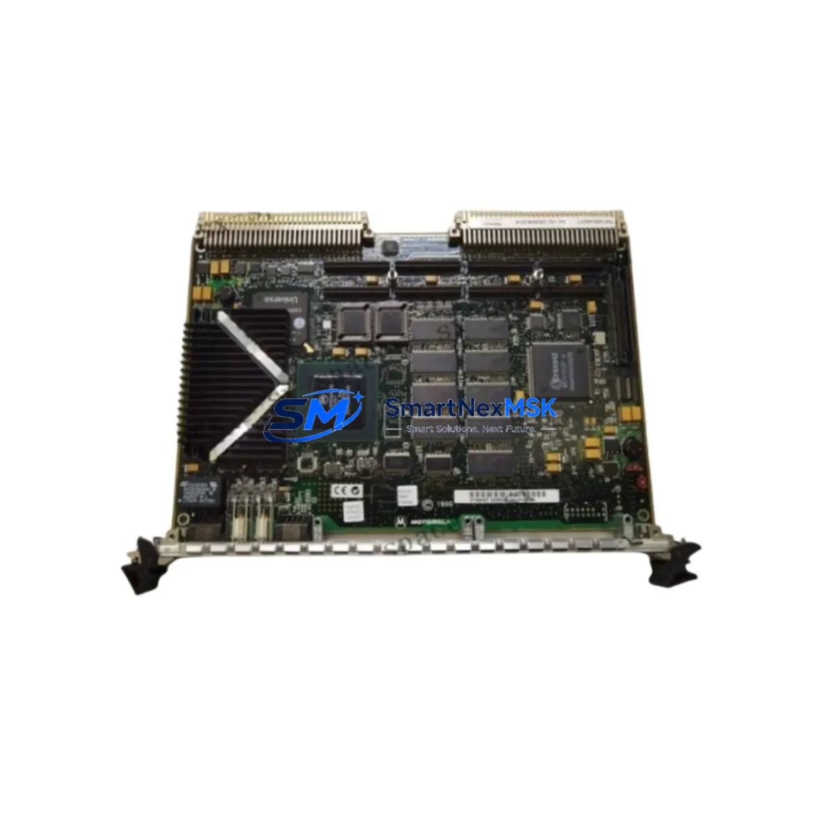
Siemens 7KK1200-4AD11 C73249-A97-B79-2 SIMOVERT Spare: Spare Replacement & Industrial Downtime Risk Control
The Siemens 7KK1200-4AD11 C73249-A97-B79-2 is an original drive control board designed for the SIMOVERT MASTERDRIVES series — one of Siemens’ most widely deployed AC variable-frequency drive platforms in industrial automation. This board serves as the central processing and control interface within the drive unit, managing PWM signal generation, motor speed regulation, fault diagnostics, and communication with upstream PLC or DCS systems. When this component fails, the entire drive axis goes offline, triggering unplanned downtime that can cascade across production lines, conveyor systems, pump stations, or HVAC control loops.
Sourced as an original Siemens spare, this 7KK1200-4AD11 C73249-A97-B79-2 board is fully tested prior to shipment and backed by a 12-month warranty. It is intended for maintenance engineers and procurement teams managing aging SIMOVERT MASTERDRIVES installations who require a verified, drop-in replacement without the lead times associated with new drive procurement or OEM repair cycles.
Spare Maintenance Table
| Parameter | Specification / Detail |
|---|---|
| Part Number | 7KK1200-4AD11 / C73249-A97-B79-2 |
| Brand | Siemens |
| Series | SIMOVERT MASTERDRIVES (6SE70 / 6SE71 platform) |
| Component Type | Drive Control Board (CU / Control Unit PCB) |
| Application | AC Variable Frequency Drive — motor speed control, torque regulation, fault management |
| Compatible Drive Frames | SIMOVERT MASTERDRIVES MC / VC / FC series (verify frame size and firmware revision before installation) |
| Communication Interface | PROFIBUS-DP / USS protocol (board-dependent; confirm with drive nameplate) |
| Operating Voltage | 24 VDC internal logic supply (from drive power supply board) |
| Operating Temperature | 0°C to +55°C (standard industrial enclosure) |
| Origin | Germany (Original Siemens manufacture) |
| Weight | 1,540 g (approx.) |
| Condition | Original spare — tested before shipment |
| Warranty | 12 Months from date of shipment |
| Maintenance Recommendation | Replace as a unit; do not attempt PCB-level component repair in field conditions |
| Installation Note | Back up drive parameters (P-list) via SIMOVIS or DriveMonitor before board swap; restore after replacement |
Maintenance Planning for Continuous Operation
When a SIMOVERT MASTERDRIVES control board such as the 7KK1200-4AD11 C73249-A97-B79-2 is flagged for replacement during a planned shutdown or emergency callout, experienced maintenance engineers know that the board itself is rarely the only component requiring attention. A thorough inspection of the surrounding electrical environment is essential to prevent repeat failures and ensure the replacement board operates within its rated conditions.
Begin with the 24 VDC internal power supply board (e.g., Siemens C98043-A7002 series or equivalent SIMOVERT PSU module). A degraded power supply delivering ripple or undervoltage is a leading cause of premature control board failure. Measure output voltage under load before installing the new board. Similarly, inspect the IGBT gate driver board and snubber capacitor bank — if the drive tripped on an overcurrent or short-circuit fault, these components may have absorbed transient energy that is not immediately visible.
Check all fiber optic pulse cables connecting the control board to the IGBT firing circuits. Contaminated or cracked fiber connectors introduce timing errors that mimic control board faults. Replace any discolored or brittle fiber assemblies as a precaution. The fan assembly and thermal management system should also be inspected: blocked airflow or a seized cooling fan will cause the replacement board to fail under the same thermal conditions that damaged the original.
On the I/O and signal side, verify the integrity of the analog input/output terminal block wiring (speed reference, torque feedback, process signals) and the digital I/O connections (run/stop, fault reset, direction commands). Loose or corroded terminals on the X100/X101 connector rows are a common source of intermittent faults that are misdiagnosed as board failures. If the drive communicates via PROFIBUS-DP, inspect the DP connector (9-pin Sub-D) and termination resistor status — a missing or double termination on the bus segment will prevent the replacement board from establishing communication with the upstream S7-300 or S7-400 PLC.
For sites running extended SIMOVERT installations, it is good practice to maintain a cabinet-level spare kit that includes: a spare control board (this 7KK1200-4AD11 C73249-A97-B79-2), a SIMOVERT operator panel (OP1S or SBP) for local parameter access, a set of PROFIBUS termination plugs, spare 24 VDC fuses for the control circuit, and a signal isolation module for analog reference inputs if the site uses long cable runs from the DCS marshalling cabinet. Having these components pre-staged in the control room significantly reduces mean time to repair (MTTR) during unplanned outages.
Site Replacement Workflow
Replacing the 7KK1200-4AD11 C73249-A97-B79-2 in a live SIMOVERT MASTERDRIVES installation follows a structured sequence to minimize downtime and protect the new board from installation-induced damage.
Step 1 — Parameter Backup: Before de-energizing the drive, connect a laptop running Siemens DriveMonitor or STARTER software via the RS232/USS interface or PROFIBUS adapter. Upload the complete parameter set (all P-parameters) to a file. This backup is critical — the replacement board ships with factory defaults and must be re-parameterized to match the motor data, ramp times, PID settings, and I/O assignments of the original installation.
Step 2 — Safe Isolation: Isolate the drive from the main AC supply using the upstream circuit breaker or disconnect switch. Verify isolation with a calibrated voltage tester at the DC bus terminals. Allow a minimum of 5 minutes for the DC link capacitors to discharge below 50 VDC before opening the drive cabinet. Do not rely solely on the drive’s internal discharge resistors in older SIMOVERT frames.
Step 3 — Board Removal: Photograph the existing wiring and connector positions before disconnecting. Remove the control board by releasing the retaining screws and carefully disconnecting all ribbon cables, fiber optic connectors, and terminal block plugs. Handle the replacement board by its edges — ESD precautions are mandatory.
Step 4 — Installation and Parameter Restore: Seat the new 7KK1200-4AD11 C73249-A97-B79-2 board, reconnect all connectors in reverse order, and restore the parameter backup via DriveMonitor. Verify motor data (P095–P109), ramp parameters, and communication node address before energizing.
Step 5 — Commissioning Check: Power up the drive in local mode (OP1S panel) and perform a no-load run to verify speed reference response, fault-free operation, and correct I/O signal mapping. Confirm PROFIBUS communication status (green LED on DP connector) before returning the drive to automatic/remote control from the PLC or DCS.
This workflow is compatible with both direct replacement of identical boards and cross-replacement scenarios where an older SIMOVERT firmware revision is being upgraded. Always confirm firmware compatibility between the control board and the power section before finalizing the order.
Spare Parts Support FAQ
Q1: Is the 7KK1200-4AD11 C73249-A97-B79-2 compatible with all SIMOVERT MASTERDRIVES frame sizes?
This control board is specific to certain SIMOVERT MASTERDRIVES configurations. Compatibility depends on the drive’s power rating, frame size (Compact, Chassis, or Cabinet), and firmware version. Always cross-reference the board part number against the drive’s nameplate and existing board label before ordering. Our technical team can assist with compatibility verification if you provide the full drive order number (6SE70xx-xxxxx-xxxx).
Q2: What testing is performed before shipment?
Every 7KK1200-4AD11 C73249-A97-B79-2 board is functionally tested on a compatible SIMOVERT MASTERDRIVES test bench prior to dispatch. Testing covers power-on initialization, communication interface response, I/O signal integrity, and fault register status. A test report is available upon request. The board ships in anti-static packaging with physical protection inserts.
Q3: What does the 12-month warranty cover?
The 12-month warranty covers manufacturing defects and functional failures under normal operating conditions from the date of shipment. It does not cover damage resulting from incorrect installation, overvoltage events, contamination, or operation outside the rated environmental parameters. Warranty claims are processed with photographic evidence of the installation environment and a description of the fault condition.
Q4: Can you support long-term or repeat procurement for maintenance stock programs?
Yes. We support planned maintenance procurement programs for facilities managing multiple SIMOVERT MASTERDRIVES installations. Volume pricing, reserved stock agreements, and scheduled delivery options are available. Contact our sales team to discuss a spare parts framework agreement tailored to your annual maintenance calendar and installed base.
© 2026 SMARTNEXMSK. All rights reserved.
Original Source: https://smartnexmsk.com
Contact: [email protected] | +86 18259474341



