
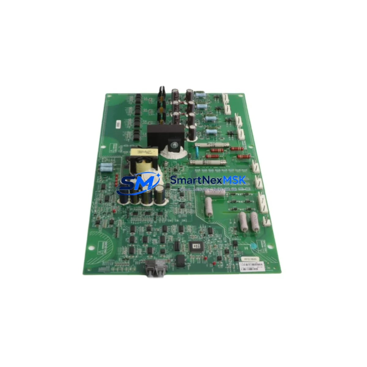
Siemens A1A10000432.71M Retrofit-Ready Control Board for SIMOREG DC Master: Compatible Upgrade for Legacy DC Drive Systems
The Siemens A1A10000432.71M is a control board designed for the SIMOREG DC Master series of DC drive converters, widely deployed in heavy industrial environments including steel mills, paper machines, extruders, winding lines, and crane systems. As the SIMOREG DC Master platform ages and original spare parts become increasingly scarce, the A1A10000432.71M has become a critical retrofit component for engineers tasked with extending the operational life of existing DC drive cabinets without full system replacement.
This board serves as a direct functional replacement for failed or end-of-life control electronics within the SIMOREG DC Master 6RA70 series. It governs the core closed-loop speed and torque regulation, firing pulse generation for the thyristor bridge, field current control, and serial communication with upstream supervisory systems. When the original board fails — often due to capacitor aging, EPROM corruption, or power surge damage — replacing it with a verified A1A10000432.71M restores full drive functionality without requiring a new drive chassis, new motor cabling, or reprogramming of the upstream PLC.
Upgrade Compatibility Table
| Parameter | Details |
|---|---|
| Compatible Drive Series | Siemens SIMOREG DC Master 6RA70 (6RA7013 to 6RA7095) |
| Board Function | Main control board — speed/torque regulation, firing pulse, field control |
| Mounting Interface | Direct backplane slot replacement; no mechanical modification required |
| Communication Compatibility | USS protocol (RS-485), PROFIBUS-DP via optional CBP2 module |
| Parameter Retention | Parameters stored in EEPROM on board; backup via DriveMonitor or STARTER recommended before swap |
| Firmware | Compatible with standard SIMOREG DC Master firmware versions; verify r-parameter set before commissioning |
| Replacement Scope | Drop-in for failed A1A10000432.71M; also replaces earlier A1A10000432.xx revisions in most applications |
| Commissioning Tool | Siemens DriveMonitor (PC-based), STARTER, or front panel PMU operator panel |
| Warranty | 12-Month Warranty — covers manufacturing defects and functional failure under normal operating conditions |
Retrofit Planning for Existing Automation Systems
A successful retrofit of the A1A10000432.71M begins well before the board is physically swapped. Engineers should first conduct a full audit of the existing SIMOREG DC Master cabinet, confirming the drive model number (e.g., 6RA7075-6DV62-0), the current firmware version displayed on the PMU operator panel, and the complete parameter set — particularly P051 (access level), P060 (fixed settings), and the closed-loop control parameters in the P100–P350 range. These should be backed up via the Siemens DriveMonitor software over the RS-232 or USS interface before any hardware is disturbed.
Power supply integrity is the next checkpoint. The SIMOREG DC Master control board draws its logic supply from the internal SMPS within the drive. Before installation, verify that the 24 VDC auxiliary supply rail and the internal ±15 VDC analog supply are within tolerance. A failing A1A10000432-SMPS power supply board is a common co-failure item and should be inspected or replaced simultaneously to avoid repeat failures on the new control board.
Terminal wiring on the X100–X177 control terminal strip must be documented with photographs and a wiring schedule before disconnection. The A1A10000432.71M uses the same terminal layout as predecessor revisions, so no rewiring is required in a like-for-like swap. However, if the retrofit is part of a broader upgrade — for example, migrating from a hardwired speed reference to a PROFIBUS-DP digital setpoint via a CBP2 communication board — the terminal assignments for analog inputs AI1/AI2 and digital inputs DI1–DI8 will need to be revised in both the wiring and the parameter set.
For sites running the SIMOREG DC Master alongside a Siemens S7-300 or S7-400 PLC, the drive typically communicates via USS over RS-485 or via PROFIBUS-DP. After board replacement, the USS node address (P918) and baud rate (P701) must be confirmed to match the PLC’s drive FB configuration — typically FB3 (USS) or the standard PROFIBUS GSD file. If the upstream controller is a Simatic S7-1500 introduced during a parallel PLC modernization, the PROFIBUS segment may need a DP/DP coupler or migration to PROFINET via a SINAMICS DCM as a longer-term path.
I/O expansion requirements should also be assessed at this stage. Many legacy SIMOREG installations use external terminal expansion modules or relay output boards mounted in the same control cabinet. These are typically wired to the X100 terminal block and are unaffected by the control board swap, but their wiring should be verified against the original electrical drawings. If the site uses a Siemens OP7 or OP17 HMI panel connected to the drive’s RS-232 port for local speed reference and fault display, the HMI communication parameters must be re-verified after the board is replaced, as the baud rate and protocol settings are stored on the control board itself.
Before energizing the drive after installation, perform a visual inspection of the thyristor firing board and the pulse transformer board (A1A10000431), which interfaces directly with the new control board. Confirm that the ribbon cable connectors are fully seated and that no standoffs or mounting screws are missing. Initial power-up should be done with the motor disconnected if possible, verifying that the drive reaches the “O” (ready) state on the PMU display without fault codes. Common post-swap faults include F002 (hardware fault), which typically indicates a seating issue, and F025 (parameter checksum error), which requires a parameter download from the backup file.
Downtime Control During System Migration
Minimizing production downtime during a SIMOREG DC Master control board replacement requires a structured pre-outage preparation protocol. The target is to complete the physical swap, parameter restore, and functional test within a single planned maintenance window — typically 4 to 8 hours for an experienced drive engineer.
The most effective downtime reduction strategy is advance preparation: have the replacement A1A10000432.71M on-site and pre-inspected before the maintenance window opens. Confirm the board revision matches the drive’s existing firmware expectations. Pre-load the parameter backup file onto the DriveMonitor laptop and verify the COM port connection to the drive’s RS-232 interface using a PC adapter USB A2 or equivalent programming cable before the outage begins.
During the outage, follow a strict sequence: isolate and lock out the main incoming supply, discharge the DC bus capacitors (minimum 5-minute wait after isolation), remove the faulty board, install the replacement, restore parameters from backup, and perform a no-load test before reconnecting the motor. If the drive is part of a multi-drive line — for example, a coordinated winder/unwinder pair where the SIMOREG DC Master operates alongside a second drive on a common DC bus — ensure the partner drive is also in a safe state before any work begins, as DC bus voltage can be present from the adjacent unit even with the local incoming supply isolated.
For critical continuous-process lines where even a planned outage carries significant cost, consider maintaining a pre-configured spare A1A10000432.71M with the site’s standard parameter set already loaded. This reduces the post-swap commissioning step to a functional verification only, cutting the outage window to under 2 hours in most cases. Our team can assist with pre-configuration and functional testing prior to shipment upon request.
Retrofit Support FAQ
Q1: Is the A1A10000432.71M a direct drop-in replacement for earlier A1A10000432 board revisions?
In the majority of SIMOREG DC Master 6RA70 applications, yes. The .71M revision is functionally compatible with earlier suffix variants (.61M, .51M, etc.) and uses the same backplane connector and terminal layout. However, if the drive was originally supplied with a specific firmware-locked board for a customer-specific application, parameter compatibility should be verified before installation. We recommend providing your drive’s full model number and existing board revision when ordering.
Q2: Do I need to reprogram the board after installation?
The replacement board ships without site-specific parameters. You must restore your backed-up parameter set using DriveMonitor or STARTER after installation. If no backup exists, parameters can be re-entered manually from the original commissioning sheet or reconstructed from the drive’s nameplate data and motor test certificate. Our technical team can assist with parameter reconstruction for standard 6RA70 applications.
Q3: What does the 12-month warranty cover?
The 12-month warranty covers manufacturing defects and functional failure under normal operating conditions from the date of shipment. It does not cover damage caused by incorrect installation, overvoltage events, contamination, or operation outside the drive’s rated environmental specifications. Warranty claims are processed with a return-and-replace procedure; advance replacement is available for critical applications subject to prior arrangement.
Q4: Can you supply the A1A10000432.71M with pre-shipment functional testing?
Yes. All boards undergo basic functional verification prior to dispatch. Extended pre-shipment testing — including parameter load, communication interface check, and simulated drive operation — is available on request. Please contact our sales team to discuss your specific testing requirements and lead time.
© 2026 SMARTNEXMSK. All rights reserved.
Original Source: https://smartnexmsk.com
Contact: [email protected] | +86 18259474341



